Using 3-Point Hitch
NOTE: The 3-point hitch on your machine is classified as a limited Category 1 hitch.
-
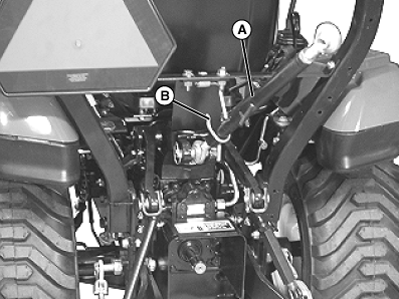
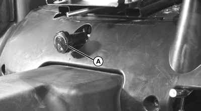
LVAL38281-UN-21AUG12A - Center Link
B - Storage Hook
Place center link (A) in storage hook (B) when hitch is not in use.
Using Rockshaft Control Lever - 1023E
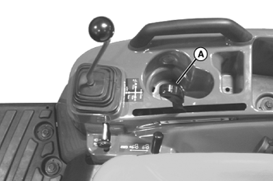
LVAL38282-UN-21AUG12
A - Rockshaft Control Lever
B - Depth Stop Lever
Use rockshaft control lever (A) to raise and lower equipment attached to the 3-point hitch.Lower Implement: Push lever forward to lower implement. Lever will automatically return to neutral position (center) when released.
Raise Implement: Pull lever rearward to raise implement. Lever will automatically return to neutral position (center) when released.
Using Rockshaft Control Lever - 1025R
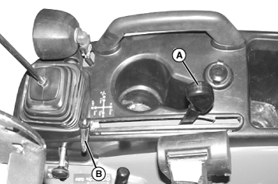
LVAL38283-UN-21AUG12
A - Rockshaft Control Lever
Use rockshaft control lever (A) to raise and lower equipment attached to the 3-point hitch.
- To lower implement: Push lever forward.
- To raise implement: Pull lever rearward.
Position control can be used to maintain the operating depth of the implement. To adjust the operating depth:
-
Unlock the depth stop lever (B) and slide toward the front of the console completely.
-
Operate the implement for several minutes to determine the desired operating depth.
-
Slide the depth stop against the rockshaft control lever and lock it in position.
-
NOTE: The calibrated label settings below the rockshaft control
lever are for reference only and do not signify specific operating
depths.
The implement will operate in same position each time the rockshaft control lever is pushed against the depth stop.
-
NOTE: The calibrated label settings below the rockshaft control
lever are for reference only and do not signify specific operating
depths.
Using Rate of Drop/Lock Valve
The rate of drop/lock valve controls the rate of rockshaft drop when the rockshaft control lever is operated. This provides direct rate of drop control for 3-point hitch mounted implements. The valve can also be used to hydraulically lock the rockshaft (three-point hitch) in a desired position.
 CAUTION: Avoid Injury! Excessive rate-of-drop may cause injury
or damage. Fully lowering implement should take at least 2 seconds.
CAUTION: Avoid Injury! Excessive rate-of-drop may cause injury
or damage. Fully lowering implement should take at least 2 seconds.
IMPORTANT: Avoid Damage! To prevent overheating hydraulic oil and damaging machine, do not raise rockshaft when drop/lock valve is closed.
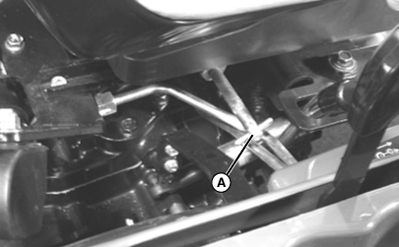
LVAL38284-UN-21AUG12
Picture Note: 1023E Shown
LVAL38285-UN-21AUG12
Picture Note: 1025R Shown
A - Drop/Lock Rate Valve Knob
Increase Rate of Drop: Rotate drop/lock rate valve knob (A) counter-clockwise to make drop faster.Decrease Rate of Drop: Rotate drop/lock rate valve knob (A) clockwise to make drop slower.
CAUTION: Avoid Injury! Do not use the rockshaft drop/lock valve
for holding an attachment in raised position for service work. Loss
of hydraulic pressure could result in sudden drop of attachment. Lower
attachment onto blocks or remove from machine before servicing.
Lock 3-Point Hitch: Rotate drop/lock rate valve knob clockwise until tight.
Unlock 3-Point Hitch: Rotate drop/lock rate knob counter-clockwise.
Using the Draft Links
-
CAUTION: Avoid Injury! Look down and behind before and while
backing. Clear area of all bystanders before backing machine.
Slowly back machine into position to align draft links with implement lift brackets.
-
Park machine safely. (See Parking Safely in Safety Section.)
-
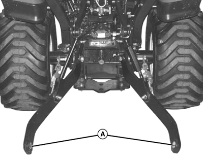
LVAL38286-UN-21AUG12A - Draft Links
Connect draft links (A) to the implement. -
Secure implement with lynch pins.
Leveling Implement Front-to-Rear
-
Park machine safely. (See Parking Safely in Safety Section.)
-
NOTE: When the 3-point hitch is not being used, return center link to storage hook (A).

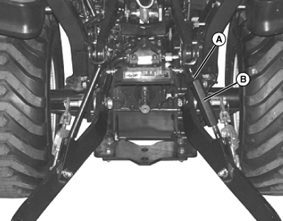
LVAL38287-UN-21AUG12A - Storage Hook
B - Locknut
C - Center Link Body
Lower implement to ground to relieve pressure on center link. -
Loosen locknut (B).
-
IMPORTANT: Avoid Damage! Do not turn center link body past the stops, or threads may be damaged.
Rotate center link body (C) to lengthen or shorten the center link as needed.
-
Tighten locknut (B).
Leveling Implement Side-to-Side
-
Lower any rear mount implement to the ground.
-
Park machine safely. (See Parking Safely in Safety Section.)
-
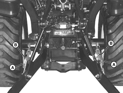
LVAL38288-UN-21AUG12A - Locknut
B - Lift Link Body
Loosen locknut (A). -
Rotate lift link body (B) to raise or lower draft link until 3-point hitch mounted implement is level from side-to-side.
-
Tighten locknut (A).
Adjusting Implement Side-to-Side Sway
-
NOTE: Check implement operator’s manual procedure for adjusting sway links. When sway links have been properly adjusted, side sway of implement is controlled by position of links.
Lower any rear mount implement to the ground.
-
Park machine safely. (See Parking Safely in Safety Section.)
-
LVAL38289-UN-21AUG12A - Locking Ring
B - Turnbuckle
Remove locking ring (A). -
Rotate turnbuckle (B) to adjust length.
-
Install locking ring.
|
KN52281,1003EC5-19-20120823 |