Install Mower
-
NOTE:
- Implements, attachments, and weights affect the set-up of the mower deck. For the initial set-up, remove all implements, attachments, and weights. After implements, attachments, or weights are installed on the mower deck, recheck to ensure that the mower deck is still level. If the deck is not level, level the deck again.
- Do not adjust the rockshaft linkage during the deck set-up. If the rockshaft linkage is adjusted during the deck set-up, level the deck again.
LV29618-UN-20DEC17
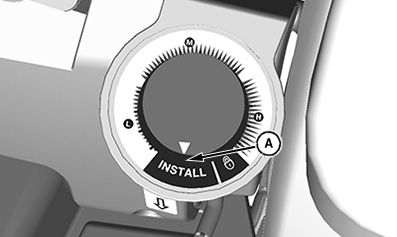
LV29888-UN-14FEB18The numbers on the control label do not represent inches. They are for reference only.
A - Install Position
Set mower height control to the install position (A). -
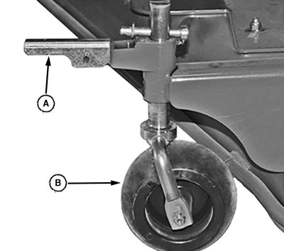
LV23990-UN-04AUG15A - Handle
B - Wheel
Raise handle (A) to release lock on each gauge wheel (B). Mower rests fully on ground. -
Ensure that mower is sitting on firm, level ground. A smooth surface allows the tractor to push the mower along the ground. Make sure that rear tires are inflated to 20 PSI.
-
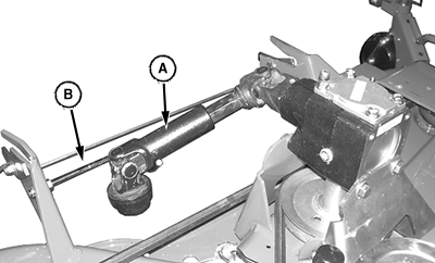
LV23991-UN-04AUG15Standard Driveshaft Models Only
A - Driveshaft
B - Hanger
Standard Driveshaft Models Only: Ensure that the driveshaft (A) is positioned in the hanger (B) on the right side of the mower. -
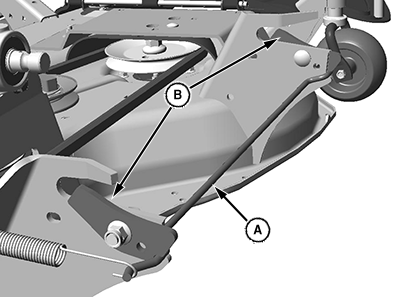
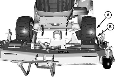
LV23992-UN-04AUG15A - Rear Lock Assembly
B - Locked
Ensure that the rear lock assembly (A) is in the locked (B) position. The lock assembly will automatically unlock as the machine engages the mower, and lock after full engagement. -
Lower mower lift arms using SCV or rockshaft lever control.
-
Shift machine PTO selector to Rear PTO only to allow the mid-PTO and driveshaft to turn freely and engage the mower gear case with minimal resistance.
-
Engage tractor MFWD, and in put low range.
-
Drive the machine straight toward rear of mower.
-
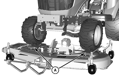
LV23993-UN-04AUG15A - Left Front Tire
B - Guide Bar
Align the outside of the left front tire (A) so it contacts the guide bar (B) on the left side of mower. -
LV23994-UN-04AUG15A - Drive-Over Ramps
Drive tractor slowly, smoothly, and straight onto the drive-over ramps (A) on mower. -
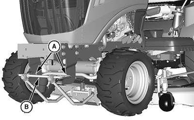
LV23995-UN-04AUG15A - Pivot Pin
B - Support Hanger
Continue driving tractor over the front edge of the mower deck until the pivot pin (A) from the draft link fully engages the notches in the front support hangers (B). Then the mower just begins to move forward. Stop the machine and lock the park brake.- If the mower pulls forward early or appears to be caught in the lift system, stop tractor, reverse sightly, and move forward again. If the mower still does not properly attach, stop the tractor, lock park brake, dismount tractor and determine cause of problem. See the troubleshooting section for additional information.
-
LV23996-UN-04AUG15A - Lock Tab
B - Rod
Dismount tractor and ensure that the rear lock tab (A) on each side of mower is raised and firmly seated against the lift arm rod (B). -
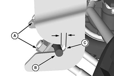
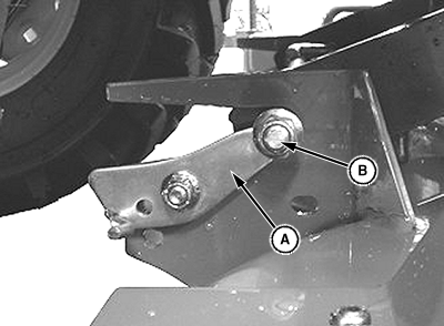
LV23997-UN-04AUG15A - Front Draft Link Nuts
B - Pivot Pin
INITIAL INSTALLATION - Adjust front draft link nuts (A) as required to achieve 3 mm (.125 in) gap between the pivot pin (B) and back of the slots (C) in the front frame hooks.- Uneven ground requires a larger gap, while level ground a smaller gap. Too much gap effects front to rear deck leveling. Too little gap causes lock to function improperly.
-
Start engine and lift mower to highest position.
-
Adjust gauge wheels as required for desired mowing height.
-
Adjust the mower height-of-cut dial to the desired setting, lower mower deck and stop the engine.
|
UP00731,0000522-19-20180815 |