Adjusting Mower Level (Side-to-Side)
-
Park machine on a flat, level surface.
-
Lock park brake.
-
Disengage mower blades.
-
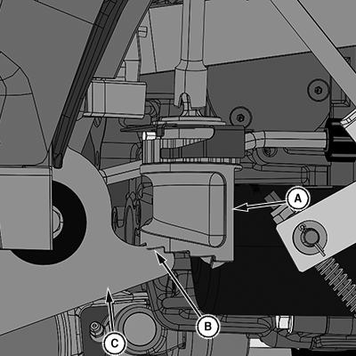
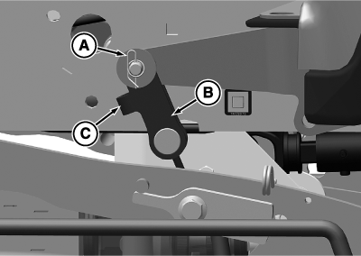
LV29980-UN-04APR18A - Height of Cut Cam
B - Fifth Step
C - Bellcrank
Raise the mower deck. Turn the height-of-cut control dial until the fifth step (B) on the height of cut cam (A) is oriented towards the bell crank (C). Lower the mower deck fully. -
 CAUTION: Rotating blades are dangerous. Before adjusting or
servicing mower:
 - To prevent the engine from starting accidentally, disconnect the negative (-) battery cable.
- Always wear gloves when handling mower blades or working near blades.
Stop the engine, remove the key, and hang a "DO NOT OPERATE" tag in the operator station.
-
Wait for the engine and all moving parts to stop before leaving the seat.
-
Disconnect the negative (-) battery cable.
-
NOTE: Do not allow the mower wheels to contact the ground during leveling.
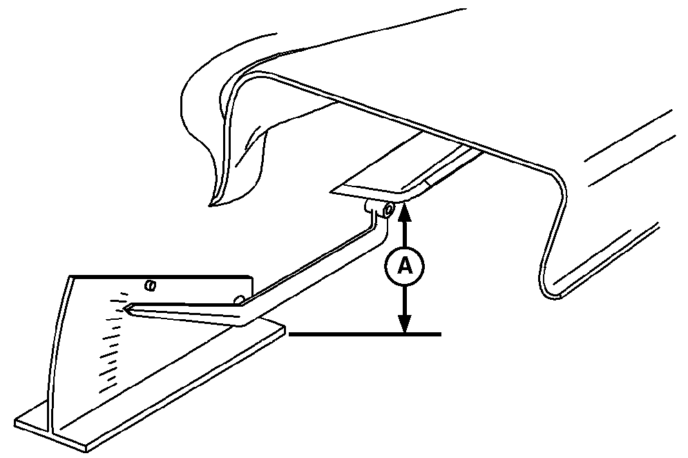
LV18692-UN-20AUG13Using Leveling Gauge
A - Level Surface
Measure from the outside blade tip to the level surface (A). -
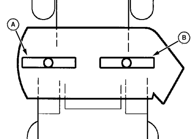
LV24008-UN-04AUG15A - Left Blade
B - Right Blade
Turn the left blade (A) as shown. Hold drive belt and turn the right blade (B) as shown. Take blade tip-to-surface measurement on both blades. The difference between both measurements must not be greater than specification.Item Measurement Specification Side-to-Side Difference 3 mm 0.125 in -
IMPORTANT: Avoid damage! For MY20— tractors, the protrusion (C) must face towards the front of the tractor to avoid damage to parts.
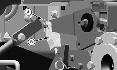
LV27024-UN-15DEC16Turnbuckle (—MY19) Shown
LV30785-UN-10AUG21Turnbuckle (MY20—) Shown
A - Retaining Pins
B - Turnbuckle
C - Protrusion
To adjust the side-to-side level:-
Remove the retaining pins (A) from the left and right rear turnbuckles (B).
-
Adjust one turnbuckle at a time, and check the blade level.
-
When adjustment is complete, install the retaining pins.
-
|
UP00731,000010C-19-20210812 |