Adjusting Deck Height
-
Ensure that the mower deck is level.
-

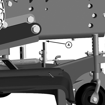
LV29984-UN-04APR18Mower Stop (2 - family tractor)

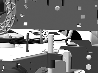
LVP11525-UN-15OCT20Mower Stop (1 - family tractor)
A - Gap
Raise the mower deck fully and measure the mower stop-to-tractor frame gap (A) between the mower lift stop and the tractor frame. Compare the measurement to specification:Item Measurement Specification Mower Stop-to-Tractor Frame Gap (A) Distance 3—13 mm 0.125—0.5 in -
If the mower stop-to-tractor frame gap is to specification, the deck adjustment is complete.
-
NOTE: If adjustments are needed beyond this point, perform the deck side-to-side and the front-to-rear procedures after the mower stop-to-tractor frame gap is successfully set.
If the mower stop-to-tractor frame gap cannot be achieved, the rockshaft linkage and or the lift strap linkage are out of adjustment. See your John Deere dealer for the proper adjustment procedure.
If the mower stop-to-tractor frame gap is not to specification:
-
Lower the mower deck to the ground.
-
Stop the engine and remove key.
-
Wait for the engine and all moving parts to stop before leaving the operator seat.
-
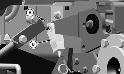
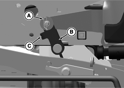
IMPORTANT: Avoid damage! For MY20— tractors, the protrusion (C) must face towards the front of the tractor to avoid damage to parts.

LV27024-UN-15DEC16Turnbuckles (—MY19) Shown

LV30785-UN-10AUG21Turnbuckle (MY20—) Shown
A - Retaining Pins
B - Turnbuckle
C - Protrusion
Remove the retaining pins (A) and pivot pin securing both turnbuckles (B) to the lift arms. -
To reduce the gap, shorten the turnbuckle assemblies an equal number of turns.
-
To increase the gap, lengthen the turnbuckle assemblies an equal number of turns.
-
Install the turnbuckles on the lift arms.
-
Raise the mower deck fully, stop engine, and remove key.
-

LV29984-UN-04APR18Mower Stop (2 - family tractor)

LVP11525-UN-15OCT20Mower Stop (1 - family tractor)
A - Gap
Measure the mower stop-to-tractor frame gap (A) between the mower lift stop and the tractor frame. Compare the measurement to specification:Item Measurement Specification Mower Lift Stop-to-Tractor Frame Gap (A) Distance 3—13 mm 0.125—0.5 in -
Repeat steps a - i until mower stop-to-tractor frame gap is to specification.
-
-
Perform the side-to-side and the front-to-rear adjustment procedure.
|
UP00731,000010D-19-20210812 |