Adjusting Mower Level (Front-to-Rear)
-
Park machine on a flat, level surface.
-
Lock the park brake.
-
Disengage the mower blades.
-
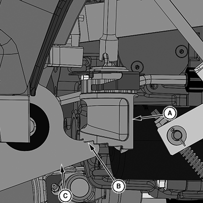
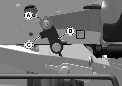
LV29980-UN-04APR18A - Height of Cut Cam
B - Fifth Step
C - Bellcrank
Raise the mower deck. Turn the height-of-cut control dial until the fifth step (B) on the height of cut cam (A) is oriented towards the bell crank (C). Lower the mower deck fully. -
 CAUTION: Rotating blades are dangerous. Before adjusting or
servicing mower:
 - To prevent the engine from starting accidentally, disconnect the negative (-) battery cable.
- Always wear gloves when handling mower blades or working near blades.
Stop the engine, remove the key, and hang a "DO NOT OPERATE" tag in the operator station.
-
Wait for the engine and all moving parts to stop before leaving the operator seat.
-
Disconnect the negative (-) battery cable.
-
NOTE: Adjust the front blade of the mower lower than the rear blade of the mower.
Do not allow the mower wheels to contact the ground during leveling.
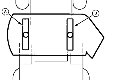
LV24010-UN-04AUG15A - Left Blade
B - Right Blade
Turn the left blade (A) as shown. Hold the drive belt and turn the right blade (B) as shown. Take blade tip-to-surface measurement on both ends of each blade and compare to specification:Item Measurement Specification Blade Tip Front-to-Rear (front is the lower end) Height Difference 3—6 mm 0.125—0.236 in -
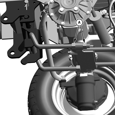
LV29982-UN-04APR18A - Draft Link Nut (4 used)
If the front-to-rear difference is within specification, tighten draft link nuts (A) and go to step 12. -
If the front-to-rear difference is greater than 13 mm (0.50 in), loosen draft link nuts (A).
-
To raise the front of the deck, shorten the draft link.
-
To lower the front of the deck, lengthen the draft link.
-
Return to step 4 to measure the front-to-rear level.
-
-
If the front-to-rear difference is less than 13 mm (0.50 in) but greater that 3 mm (0.125 in), tighten the draft link nuts (A).
-
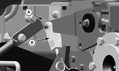
LV27024-UN-15DEC16Turnbuckle (—MY19) Shown
LV30785-UN-10AUG21Turnbuckle (MY20—) Shown
A - Retaining Pins
B - Turnbuckle
C - Protrusion
Connect the negative battery cable. -
Lower the deck to the ground, stop the engine, and remove the key.
-
IMPORTANT: Avoid damage! For MY20— tractors, the protrusion (C) must face towards the front of the tractor to avoid damage to parts.
Remove the retaining pins (A) and pivot pin securing both turnbuckles (B) to the lift arms.
-
Shorten both turnbuckle assemblies an equal number of turns to raise the rear of the deck.
-
Lengthen both turnbuckle assemblies an equal number of turns to lower the rear of the deck.
-
When the adjustment is complete, install the retaining pins.
-
Return to step 4 to measure the front-to-rear level.
-
-
Connect the negative battery cable.
-
Lower the deck to the ground, stop the engine, and remove the key.
-
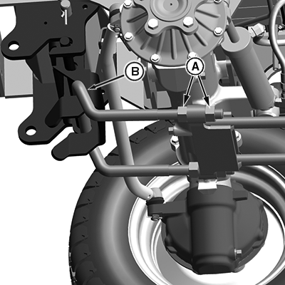
LVP11523-UN-15OCT20Draft Link (—MY19) Shown, MY20— is Similar
A - Draft Link Nut (4 used)
B - Draft Link Gap
Measure the draft link gap (B) and compare to specifications.Item Measurement Specification Draft Link Gap (B) Distance 3 mm 0.125 in -
If the draft link gap (B) is not to specification, loosen the draft link nuts (A).
-
To decrease the draft link gap, shorten the draft link.
-
To increase the draft link gap, lengthen the draft link.
-
Return to step 4 to measure the front-to-rear level.
-
-
If the draft link gap (B) is to specification, the front-to-rear leveling procedure is complete.
|
UP00731,0000373-19-20210812 |