Install Mower
-
NOTE: If equipped, remove the front weights before installing the mower deck. Replace the weights after the mower deck is installed.
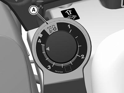
LVP11309-UN-09SEP20Numeric Label (1 - family shown, 2 - family is similar)
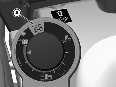
LVP11152-UN-19AUG20Symbolic Label (1 - family shown, 2 - family is similar)
A - Install Position
Set the mower height control to the install position (A). -
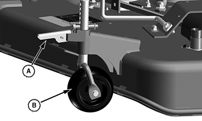
LV27027-UN-09DEC16A - Handle
B - Wheel
Raise handle (A) to release the lock on each gauge wheel (B). The mower rests fully on the ground. -
Ensure that the mower deck is sitting on firm, level ground. A smooth surface allows the mower to be pushed along by the tractor. Inflate tires to 20 PSI.
-
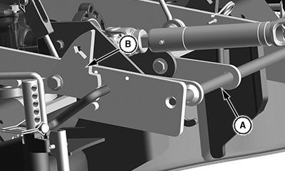
LV27143-UN-16DEC16Rear Lock Assembly (—MY19)
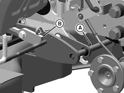
LVP11520-UN-15OCT20Rear Lock Assembly (MY20—)
A - Rear Lock Assembly
B - Locked Position
Ensure the rear lock assembly (A) is in the locked position (B). The lock assembly automatically unlocks as the machine engages the mower, and locks after full engagement. -
Lower the mower lift arms using the SCV or the rockshaft lever control.
-
Shift the machine PTO selector to the rear PTO to allow the mid-PTO and driveshaft to turn freely and engage the mower gear case with minimal resistance.
-
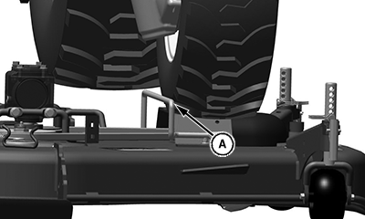
LV27016-UN-09DEC16Mower Deck (—MY19) Shown, MY20— is Similar
A - Guide Bar
Engage the tractor MFWD with the machine in low range. Drive the machine straight toward the rear of the mower while aligning the inside of the left front tire with the guide bar (A). -
Drive the tractor onto the mower deck with the inside of the left tire against the guide bar.
-
Slowly drive the tractor forward until the mower begins to pull along ground for approximately 102 mm (4 inches) behind front wheels.
-
If mower deck pulls forward early or appears to be caught in the lift system, stop the tractor, reverse slightly, and move forward again. If mower deck still does not properly attach, stop the tractor, lock the park brake, dismount the tractor, and determine the cause of the problem.
-
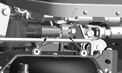
LV27020-UN-09DEC16A - PTO Coupler
B - Gear Box Coupler
PTO coupler (A) aligns with the gear box coupler (B). -
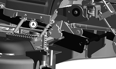
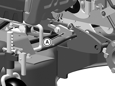
LV27019-UN-09DEC16—MY19
LVP11521-UN-15OCT20MY20—
A - Lock
Dismount the tractor and ensure locks (A) on both sides have dropped to the locked position. If necessary, pull the mower rearward to engage the lock and the coupler. On first installation, mower may not lock in position if front link is too short. -
Install the cotter pins in the locked position.
-
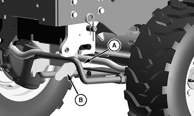
LV27018-UN-13DEC16Forward Link —MY19) Shown, MY20— is Similar
A - Forward Lift Link
B - Hanger
Make sure the forward lift link (A) is nested into the hangers (B) per specification.Item Measurement Specification Forward Lift Link (A) Gap 3 mm 0.125 in -
Start the engine and lift the mower to full height.
-
Lock down all gage wheels by snapping the handles down and ensuring the lock pins are fully seated in the vertical rods.
|
UP00731,0000A0F-19-20201016 |