Check and Adjust Toe-In
- Stop the machine on a firm, level surface.
- Disengage the MFWD if equipped.
- Turn the steering wheel so the front wheels are pointing straight ahead.
- Park the machine safely.
Check Toe-In
NOTE: Use an outside or inside bar on each tire for marking the center line if the front axle is equipped with bar tires.
-
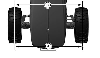
LV26019-UN-25AUG16A - Distance between center line of tire.
B - Distance between center line of tire.
Using chalk, mark the center line of each tire at hub height and to the front of the axle. - Measure and record the distance (A) between the center lines of each tire.
- Drive the machine forward or rearward until the chalk mark moves 180° to rear of the axle.
- Park the machine safely.
- Measure and record the distance (B) between the center lines of each tire.
- Determine the difference between the front and rear measurement. The measured distance (A) must be 3 mm (1/8 in) less than the measured distance (B). Adjust the toe-in if necessary.
Adjust Toe-In
-
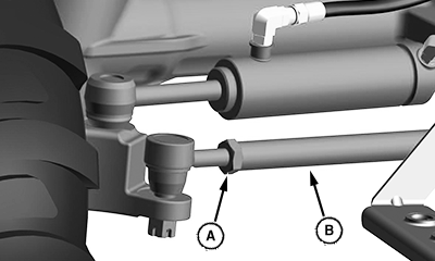
LV25631-UN-15JUN16A - Nut
B - Tie Rod
Loosen nuts (A) on both ball joints. -
Rotate the tie rod (B) clockwise or counterclockwise to adjust
the amount of toe-in. Adjust the tie rod until the toe-in measurement
is within the correct specification.
- Rotating the threaded rod in 1/2 turn increments equals 1.5 mm (1/16 in).
-
Tighten the nuts to the correct specification. ().
Item Measurement Specification Ball Joint Nut Torque 120 N·m 88 lb·ft - Check the toe-in setting. Repeat the procedure if further adjustment is required.
|
UP00731,00001CB-19-20180103 |