Replace Brush Sections
Remove Old Brush Sections
Avoid damage! Replace brush sections when worn to 23 cm (9 in) in diameter.
LV27586-UN-02FEB17
LV27587-UN-02FEB17
LV27588-UN-02FEB17
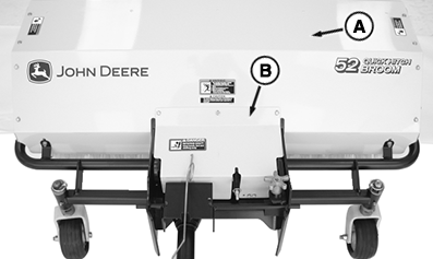
A - Main Shield
B - Gearbox Shield
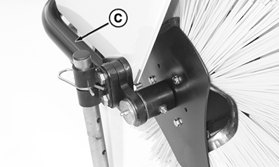
C - Parking Stand Crossbar
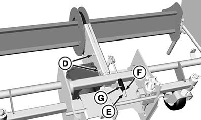
D - Bolts and Locknuts
E - Nut
F - Washer
G - Spring
-
Park machine safely.
-
Remove all bolts in main shield (A). Remove main shield with gearbox shield (B).
-
Block broom or support broom with a suitable lifting device at area just behind parking stands (C).
-
Brush sections removed from core.
Remove bolts and locknuts (D) in chain guard. Remove chain guard.
-
Remove nut (E), washer (F) and spring (G) from idler tension bolt.
-
LV27589-UN-02FEB17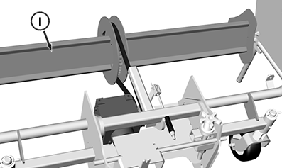
LV27590-UN-02FEB17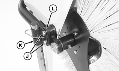
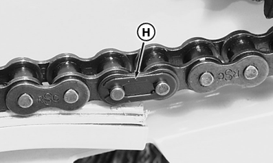
LV27591-UN-02FEB17H - Master Link Retaining Clip
I - Support Core
J - Bolts (2 used)
K - Brackets
L - Spacers
Locate master link retaining clip (H) on drive chain. Remove and retain the clip. -
Remove master link to disconnect chain. Retain master link and remove the chain.
-
Brush sections removed from core.
Support core (I) near both ends with a suitable lifting device.
-
Remove two bolts (J) and nuts attaching parking stand to broom. Remove brackets (K) and spacer (L) on both sides of broom. Remove core with brush sections from broom.
-
Brush sections shown installed on core on broom.
LV27592-UN-02FEB17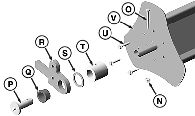
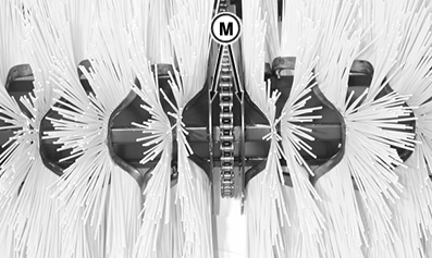
LV27593-UN-02FEB17M - Inside Retainer Plate
N - Locknut
O - Shear Bolt
P - Core Pin
Q - Flange Bearing
R - Core Retainer
S - Thrust Bearing
T - Tube
U - Screws (3 used)
V - Retainer Plate
Twelve brush sections are installed on both sides of the core. Note the brush section installation sequence for each side:-
Slide the first brush section onto the core against the inside retainer plate (M) as shown.
-
Slide eleven additional brush sections onto the core in an alternating pattern.
-
-
Remove locknut (N) and shear bolt (O). Remove core pin (P), flange bearing (Q), core retainer (R), thrust bearing (S), tube (T) and three screws (U). Remove retainer plate (V).
-
 Avoid injury! Brush bristles can be sharp. Wear heavy
gloves when handling the brush head.
Remove brush sections from core.
Install New Brush Sections
LV27594-UN-02FEB17
LV27595-UN-02FEB17
LV27596-UN-02FEB17
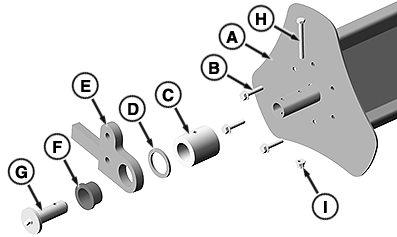
A - Retainer Plate
B - Screws (3 used)
C - Tube
D - Thrust Bearing
E - Core Retainer
F - Flange Bearing
G - Core Pin
H - Shear Bolt
I - Locknut
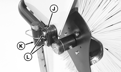
J - Spacers
K - Parking Stand Brackets
L - Bolts and Nuts (2 used)
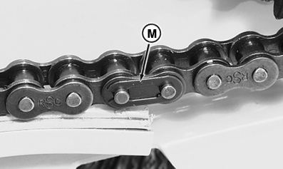
M - Master Link Retaining Clip
-
Replace bush sections as needed in correct installation sequence.
-
Install retainer plate (A) on core with three screws (B).
-
Install tube (C), thrust bearing (D), core retainer (E), flange bearing (F), core pin (G), shear bolt (H) and locknut (I).
-
Install broom core, spacers (J) and parking stand brackets (K) with two bolts (L) and nuts.
-
Install and connect drive chain with master link and retaining clip (M).
-
Brush sections removed from core.
LV27597-UN-02FEB17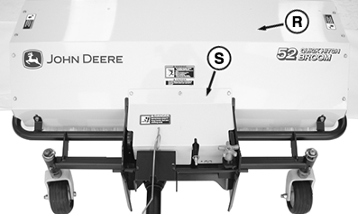
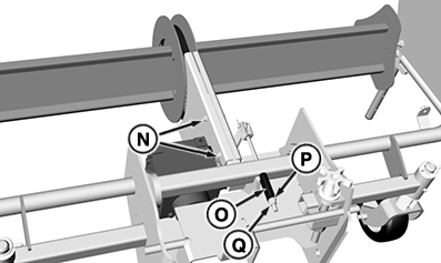
LV27598-UN-02FEB17N - Bolts and Locknuts
O - Spring
P - Washer
Q - Nut
R - Main Shield
S - Gearbox Shield
Install chain guard with bolts and locknuts (N). -
Install spring (O), washer (P) and nut (Q) on idler tension bolt.
-
Install main shield (R) with gearbox shield (S).
|
DB71512,00001A4-19-20170202 |