Use 3-Point Hitch
The 3-point hitch on your machine is classified as a category I hitch.
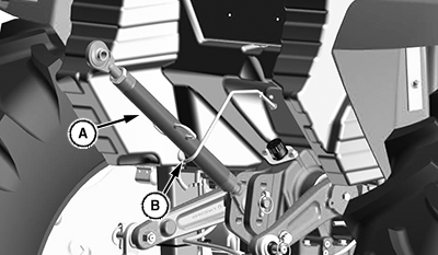
Center Link Storage Position
LV28323-UN-12JUL17
A - Center Link
B - Storage Hook
Place center link (A) in storage hook (B) when hitch is not in use.
Position Center Link
-
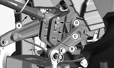
LV28081-UN-03APR17A - Center Link
B - Bottom Hole
C - Middle Hole
D - Top Hole
For light and medium draft loads: Install center link (A) in bottom hole (B) of mounting bracket. Example of a light or medium draft load implement is a landscape rake. A category I implement tilts forward while rising in this position.
- For medium and heavy draft loads: Install center link in middle hole (C) of mounting bracket. Example of a medium or heavy draft load implement is a tiller or box blade. A category I implement tilts forward slightly while rising in this position.
- For very heavy draft loads: Install center link in top hole (D) of mounting bracket. Example of a very heavy draft load implement is a plow or ripper. A category I implement rises, but angle remains constant.
Use the Draft Links
-
 Avoid injury! Look down and behind before and while
backing. Clear area of all bystanders before backing machine.
Avoid injury! Look down and behind before and while
backing. Clear area of all bystanders before backing machine.Slowly back machine into position to align draft links with implement lift brackets.
-
Park machine safely.
-
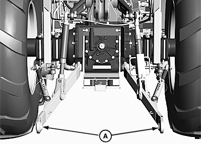
LV20866-UN-03FEB14A - Draft Links
Connect draft links (A) to the implement. -
Secure implement with quick lock pins.
Telescoping Draft Link (Optional)

LV18421-UN-19JUL13
A - Locking Lever
B - Link
Avoid injury! Fingers and hands can be pinched or crushed.
Be aware of potential pinch points and keep hands away.
Avoid damage! Telescoping draft link locking levers must be in locked position before operating the machine, or link damage could occur.
Machines equipped with optional telescoping draft links can be connected two different ways.
Option 1
-
Slowly back machine into position to align draft links with implement lift brackets.
-
Park machine safely.
-
Raise locking lever (A) and pull link (B) to extend as needed.
-
Connect draft links to the implement.
Option 2
-
Sit on operator’s seat and start engine.
-
Back machine until each lock lever snaps and secures each draft link in the locked position.
Adjust Draft Links to Float Position

LV18422-UN-19JUL13
Float Position
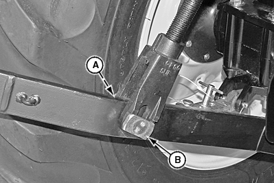
LV18423-UN-19JUL13
Rigid Position
A - Spring Locking Pin
B - Stop Pin
Adjusting 3-point hitch stops to the float position will allow both draft links to rise slightly as the implement follows ground contour.
Adjust stops to the float position for 3-point hitch implement such as a cultivator or mower. These implements have ground gauging skids or wheels, which may otherwise cause the implement to twist relative to the machine.
-
Park machine safely.
-
Remove spring locking pin (A) and rotate stop pin (B) 90 degrees to position shown.
Adjusting Draft Links to Rigid Position
Adjusting 3-point hitch stops to the rigid position will restrict movement of the draft links as the implement follows ground contour.
Adjust stops to the rigid position for 3-point hitch implements such as plows and ground engaging implements that should not twist relative to the machine.
-
Park machine safely.
-
Remove spring locking pin (A) and rotate stop pin (B) 90 degrees to position shown.
|
UP00731,00002A5-19-20170619 |