Use Front 3-Point Hitch (If equipped)
Installing Lift Arms
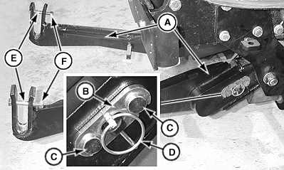
LV19383-UN-18OCT13
A - Lift Arms
B - Plate
C - Pins
D - Lynch Pin
E - Lift Arm Screws
F - Lift Arm Locknuts
Install lift arms (A) on pivot bracket with pin retainer plate (B), two lift arm retention pins (C) and lynch pin (D).Assemble A-Frame
List of parts for reference:
-
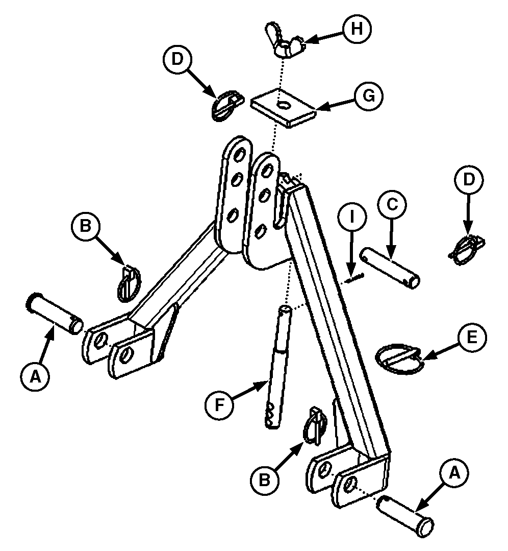
LV19384-UN-18OCT13A - Cylinder Pin
B - Lynch Pin
C - Hinge Pin
D - Lynch Pin
E - Quick Lock Pin
F - Retainer Rod
G - Retainer Plate
H - Wing Nut
I - Cotter Pin
Install cylinder pins (A) in frame with lynch pins (B). -
Install hinge pin (C) in middle hole in frame with lynch pins (D).
-
Install quick-lock pin (E) in retainer rod (F). Install retainer rod on frame with retainer plate (G), wing nut (H) and cotter pin (I).
Install A-Frame
-
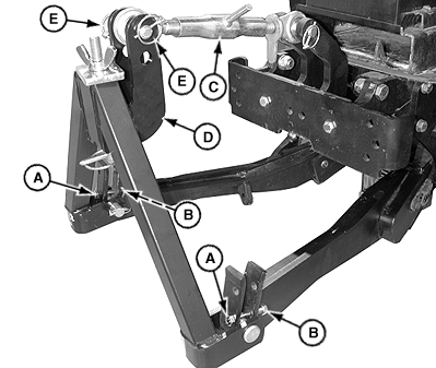
LV19385-UN-18OCT13A - Screws
B - Locknuts
C - Center Link
D - Hinge Pin
E - Lynch Pins
Remove screws (A) and locknuts (B) in front hitch lift arms. -
Install A-frame on lift arms as shown.
-
Install front hitch center link (C) on A-frame with hinge pin (D) and lynch pins (E).
- Center link may be installed on top or middle hole in A-frame to allow for more or less implement tilt.
-
Install screws (A) and locknuts (B) in front hitch lift arms.
- Install screws in top holes in lift arms for implement float position.
- Install screws in bottom holes in lift arms for implement fixed position.
Installing Implements on Front Hitch with A-Frame
Installing Implement:
-
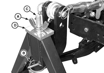
LV19386-UN-18OCT13A - Wing Nut
B - Quick Lock Pin
C - Retainer Rod
D - Retainer Plate
Loosen wing nut (A) and remove quick-lock pin (B). -
Remove retainer rod (C) with wing nut and retainer plate (D) from A-frame.
-
Check to be sure that the implement hydraulic hoses are out of the way if applicable.
-
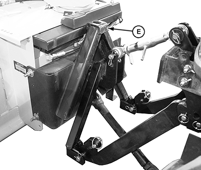
LV19387-UN-18OCT13E - Mount
Drive tractor forward slowly and align A-frame with mount (E) on implement. -
Raise hitch to install A-frame on mount.
-
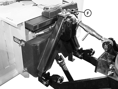
LV19388-UN-18OCT13F - Wing Nut
Install retainer rod with wing nut and retainer plate through mount and A-frame. Position wing nut (F) as needed to install quick-lock pin in retainer rod. -
Tighten wing nut to secure implement to A-Frame.
Installing and Removing Mid-Mount Mower
Assemble and Install Front Draft Pivot Assembly:
-
Park machine safely.
-
Follow installing instructions in mid-mount mower operator’s manual.
-
Remove yokes installed on front draft pivot assembly supplied with mid-mount mower.
-
Remove spring locking pins, J-pins and springs on front of mower.
-
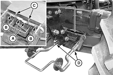
LV19389-UN-18OCT13A - J-Pins
B - Locking Pins
C - Cotter Pins
D - Yokes
Install J-pins (A), spring locking pins (B) and cotter pins (C) on front of mower as shown. -
Install yokes (D) on front draft pivot assembly for front hitch. Thread yokes 2.5 cm (1 in.) onto rods.
-
Install front draft pivot assembly on mower as shown. Check to be sure J-pins are locked.
-
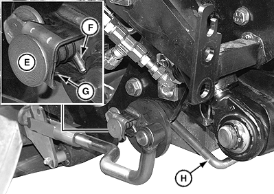
LV19390-UN-18OCT13E - Drilled Pin
F - Roll Pin
G - Notch
H - Shaft
Pull back on drilled pin (E) on front draft pivot assembly and insert roll pin (F) into notch (G). -
Install front draft pivot assembly on front hitch as shown.
-
Move pivot shaft (H) upward until the drilled pin snaps into hole.
-
Follow the adjusting upstop clearance instructions in mid-mount mower operator’s manual.
Removing Mid-Mount Mower:
-
Park machine safely.
-
Following removing mower instructions in mid-mount mower operator’s manual.
-
Pull back on drilled pin on front draft pivot assembly and insert roll pin into notch.
-
Move pivot shaft downward and remove front draft pivot assembly from front hitch.
-
Pull both J-pins on front of mower outward and turn to unlocked position.
-
Remove front draft pivot assembly from mower brackets and out from under tractor.
-
Follow remaining Removing Mower instructions in mid-mount mower operator’s manual to move mower out from under tractor.
Operating Front Hitch
Raising and Lowering Hitch
-
Check to be sure hitch is not in transport lock position.
-
Review instructions on using hydraulic dual selective control valve (SCV) and dual selective control valve lock lever included in your tractor operator’s manual.
-
Move the tractor dual SCV lever:
-
To raise the hitch, move the lever rearward.
-
To lower the hitch, move the lever forward.
-
Adjusting Hitch Control Valve
-
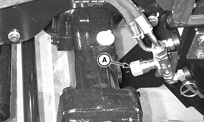
LV19414-UN-18OCT13A - Knob
Rotate knob (A) on valve to adjust the speed at which the hitch raises and lowers. - Rotate knob (A) to close the valve and place the hitch in transport lock position.
Removing and Storing
Removing Implement
-
Park machine safely.
-
Loosen wing nut.
-
Remove quick-lock pin in retainer rod.
-
Remove retainer rod with retainer plate.
-
Lower the hitch to remove A-frame from implement mount, and slowly back tractor away from implement.
-
Install retainer rod with retainer plate on A-frame with quick-lock pin.
Removing A-frame
-
Remove locknuts and screws in front hitch lift arms.
-
Remove lynch pins and hinge pin and remove front hitch center link from A-frame. Remove A-frame.
-
Install screws and locknuts in front hitch lift arms.
Removing Hitch
- Front hitch may be left on tractor when not in use.
- Lift arms should be removed when front hitch is not in use, and must be removed for loader operation.
- Lift arms and center link may be removed and stored.
-
To remove front hitch, reverse the order of assembly:
- Remove lift arms.
- Remove hydraulic hoses.
- Remove center link.
- Remove front PTO support.
- Remove hydraulic cylinder.
- Remove pivot bracket and mount brackets.
Storing
-
Lift arms should be removed when front hitch is not in use.
Remove lynch pins, pin retainer plates and lift arm retention pins, and remove lift arms from lower pivot bracket.
-
Store plates and pins in lower pivot bracket.
-
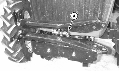
LV19391-UN-18OCT13A - Link Pin
Use link pin (A) and two lynch pins to secure lift arms to center link bracket.
Storing Center Link
-
Remove A-frame from front hitch.
-
Remove link pin and two lynch pins to remove center link from center link bracket.
-
Store link pin and lynch pins in center link bracket.
-
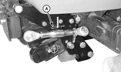
LV19392-UN-18OCT13A - Locking Pin
Install center link on mount on left mount bracket with spring locking pin (A).
|
UP00731,00000D4-19-20171012 |