Attach Backhoe to Tractor
 CAUTION:
X9811-UN-23AUG88
If an accident occurs, see a doctor immediately. Any fluid injected into the skin must be surgically removed within a few hours or gangrene may result. Doctors unfamiliar with this type of injury should reference a knowledgeable medical source. Such information is available from Deere & Company Medical Department in Moline, Illinois, U.S.A.
CAUTION: Operator must be seated in tractor seat when positioning
tractor for backhoe installation.
-
LV29809-UN-12DEC17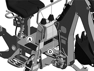
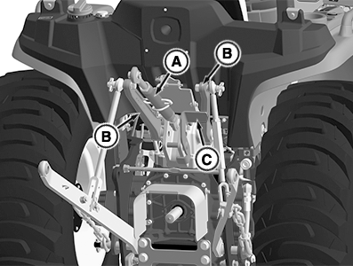
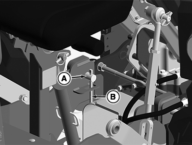
LV29813-UN-12DEC17A - Center Link
B - Lift Arm Stop
C - 3-Point Hitch Assembly
D - Swing Pin
Park tractor safely on a flat level surface. -
Remove and install the center link (A) to storage hanger on the backhoe seat frame.
-
Raise tractor 3-point hitch assembly (B).
-
Install lift arm stop (C).
-
Raise backhoe seat to clear the machine.
-
IMPORTANT: Avoid damage to tractor and hydraulic hose. Check to be sure that all hydraulic hoses are routed away from pinch points before installing backhoe to tractor.
Start engine and run at low idle.
-
Back up the tractor to within 8 inches of backhoe.
-
Stop tractor engine and engage park brake.
-
Verify swing pin (D) is installed, if not, install.
-
CAUTION: To avoid injury from escaping fluid under pressure,
stop engine and relieve the pressure in the system before disconnecting
or connecting hydraulic or other lines. Tighten all connections before
applying pressure.
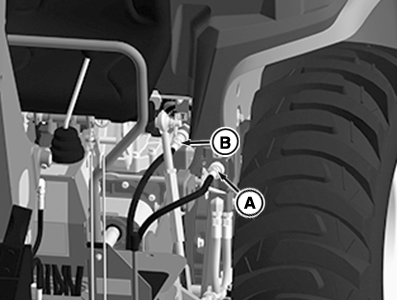
LV29810-UN-13DEC17A - Backhoe Hydraulic Supply Line Coupler
B - Backhoe Hydraulic Tank Line Coupler
Disconnect tractor power beyond hydraulic coupler behind tractor. -
Connect backhoe hydraulic supply and tank line couplers (A and B) to machine couplers.
-
Place power beyond hose in the storage hanger below the supply coupler.
-
Start tractor and set engine to low idle.
-
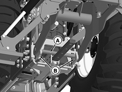
LV29811-UN-13DEC17A - Lower Backhoe Frame Bar
B - Hook Slot (2 used)
Lower backhoe stabilizers to raise the backhoe until lower shaft (A) is above hooks (B). -
Back up tractor until lower shaft (A) contacts machine frame.
-
Lower stabilizers until lower shaft (A) rests in hooks (B).
-
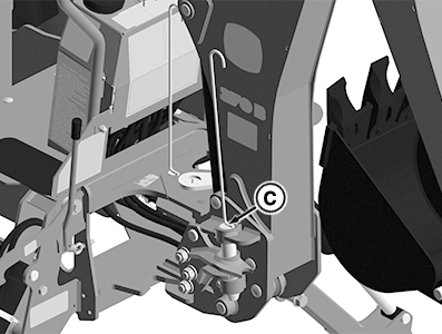
LV29814-UN-13DEC17C - Boom Lock Pin
Remove boom lock pin (C). -
Lower backhoe boom until cross holes in mount frame and backhoe align.
-
LV29812-UN-13DEC17A - Lock Pin (2 used)
B - Retainer Pin (2 used)
Install lock pin (A) through backhoe and mount frame from inside on right-hand and left-hand sides. -
Install retainer pin (B) on right-hand and left-hand sides.
-
From the backhoe operator seat, bleed the hydraulic system by doing the following:
-
Check to be sure that operating area is clear.
-
Raise and lower both stabilizers.
-
Raise and lower boom.
-
Extend and retract the dipperstick.
-
Curl and dump the bucket.
-
Swing boom from side to side.
-
-
LV29815-UN-13DEC17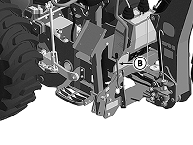
LV29816-UN-13DEC17Right-Hand Side shown; Left-Hand Side Similar
A - Boom Lock Pin
B - Stabilizer Lock (2 used)
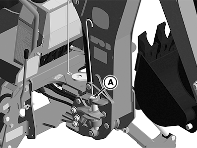
Raise backhoe to transport position and install boom lock pin (A). -
Raise stabilizers and lock by pulling stabilizer locks (B) on both sides.
|
UP00731,00004FB-19-20180105 |