Removing Snowblower
MXT007364-UN-29MAY13
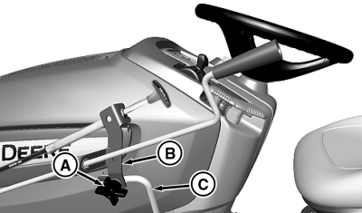
A - Knob
B - Chute and Spount Bracket
C - Rotation Handle Bracket
NOTE: X300R and X305R only - The inner lift rod (shorter of the two lift rods), installed as part of the snowblower front lift assembly, must be removed before installing the mower deck to avoid interference with the fan housing. Store inner lift rod with other snowblower components to avoid loss during the off-season, and install again prior to seasonal installation of the snowblower, if applicable.
-
Park machine safely. (See Parking Safely in Safety section.)
-
 CAUTION: Avoid injury! Attachment can lower rapidly.
Attachment is heavy and can crush. Keep bystanders, especially children, away when lowering attachment.
Support raised attachment with a mechanical stop or lower completely to the ground before servicing.
Raise and block-up the snowblower.
-
Remove drive belt from machine drive sheave.
-
Remove block and lower snowblower.
-
Remove knob (A), and retaining hardware securing chute and spout bracket (B) to rotation handle bracket (C). Install knob and hardware back into bracket (B) for storage, then pivot bracket with chute and spout controls away from machine.
-
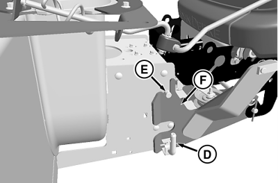
MXT007365-UN-29MAY13D - L-Pin
E - Pin
F - Front Hitch Assembly
To remove just snowblower, pull out L-pins (D), on each side, and pull snowblower assembly up to disengage two pins (E) from slots at top of front hitch assembly (F). Remove snowblower from machine, and pivot or tilt chute and spout controls out of the way for storage.NOTE: Install pins, locking ring, and spring locking pin in front hitch assembly for storage.
-
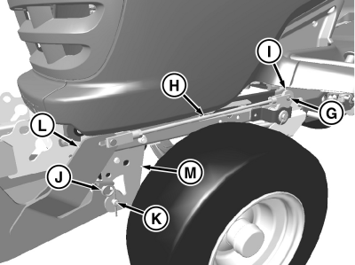
MXT007366-UN-29MAY13G - Drilled Pin, M10 x 28
H - Lift Rod
I - Rockshaft Bracket
J - Spring Locking Pin, M4.5 x 90
K - Front Draft Pin
L - Front Hitch
M - Front Draft Assembly
To also remove front hitch assembly, remove rear locking ring and M10 x 28 drilled pin (G), and remove rear yoke of lift rod (H) from rockshaft bracket (I). -
Remove M4.5 x 90 spring locking pin (J) and front draft pin (K), and remove front hitch (L) from front draft assembly (M).
-
CAUTION: Avoid injury! When the attachment is removed, also
remove any ballast that was added to the machine.
Use only attachments and accessories recommended by the manufacturer.
Remove any weights that were installed when preparing machine.
|
TH84124,0000146-19-20130617 |