Installing Mower
Installing Mower—Two Wheel Drive Tractor
-
Park machine safely in front of mower deck with rear wheels facing the mower deck. (See Parking Safely in the SAFETY section.)
-
 CAUTION: Avoid injury! Servicing a machine while the engine
is running is dangerous.
CAUTION: Avoid injury! Servicing a machine while the engine
is running is dangerous.• Engine exhaust fumes contain carbon monoxide and can cause serious illness or death. Do not run an engine in an enclosed area without adequate ventilation.
• Be cautious and wear protective clothing when servicing or working near a hot engine and components.
• Keep hands, clothing, jewelry and long hair away from moving parts.
Start engine, and pull back top hydraulic lever (A) to raise lift arms to highest position.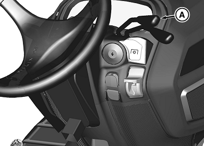
MXT009242-UN-21SEP13 -
Adjust mower height control knob to lowest cutting position.
-
Position mower on a hard and level surface. Move all four mower wheel quick release pin levers (B) to the horizontal position to ensure mower deck shell is sitting flat on surface.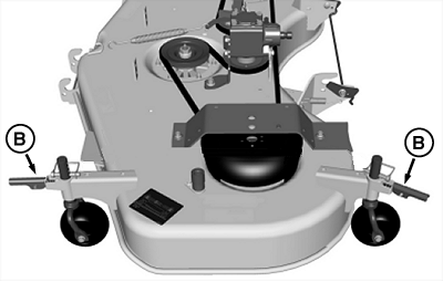
MXT009243-UN-21SEP13 -
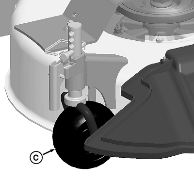
If using a standard PTO shaft connection, ensure PTO shaft on deck is positioned on hanger (C), clear of where the rear draft arms fit into rear brackets on deck.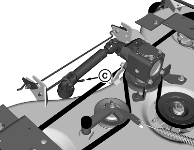
MXT009244-UN-21SEP13 -
Line up rear tires with plates (D) on front of deck, and increase engine speed to full throttle.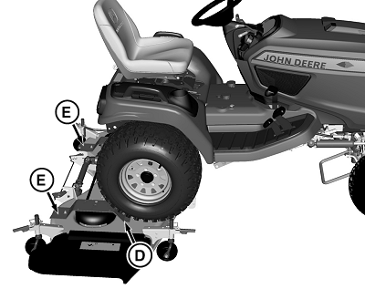
MXT009245-UN-21SEP13 -
Back machine over the middle of deck ramps (E). Continue backing up until the rear tires are over the mower deck and the front tires contact the front plates on deck.
-
Push top hydraulic lever (A) forward to lower rear draft arms.
-
Drive forward to engage rear draft arms (F) into deck brackets (G), stop once deck begins to be pushed forward.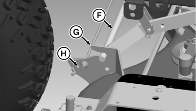
MXT009246-UN-21SEP13 -
Turn off engine and set the park brake.
-
Check to make sure rear draft lock (H) is in the up position, securing the rear draft arms (F) of the tractor within the rear deck brackets (G). Manually rotate draft lock on deck if necessary to complete the connection.
-
Install front deck hanger (I) through front hooks on deck, then onto the hooks on the vehicle frame. If necessary, manually rotate draft lock from right side of tractor to complete the connection.
MXT009247-UN-21SEP13 -
Move release latch (J) up and lock pin into hole on frame.
-
NOTE: If auto connect coupler does not line up with gearbox input shaft, see Adjusting Auto Connect Coupler.
If using a standard PTO shaft connection, hook up coupler on deck PTO driveshaft (K) to the stub shaft on the transmission. When coupler locks onto stub shaft, push coupler fully forward and then pull backward to make sure coupler is latched.
MXT009249-UN-21SEP13 -
Start engine and pull back on top hydraulic lever to raise deck to highest position.
-
Adjust mower height control knob to desired setting.
-
Lower deck by pushing forward on the top hydraulic lever.
-
Turn off engine and set park brake.
-
NOTE: Bottom of anti-scalping wheels should be approximately 6 -13 mm (1/4 - 1/2 in.) from ground.
Turn quick release pin levers (L) to horizontal (open) position. Move anti-scalping wheels to desired operating position, and lower quick release pin levers to lock in place.
MXT009250-UN-21SEP13 -
Install locking pins (M) in lowest shaft hole above wheel bracket to keep same height setting for later mower installations.
Installing Mower—Four Wheel Drive Tractor
-
Park machine safely behind mower deck with front wheels facing the mower deck. (See Parking Safely in the SAFETY section.)
-
CAUTION: Avoid injury! Servicing a machine while the engine
is running is dangerous.
• Engine exhaust fumes contain carbon monoxide and can cause serious illness or death. Do not run an engine in an enclosed area without adequate ventilation.
• Be cautious and wear protective clothing when servicing or working near a hot engine and components.
• Keep hands, clothing, jewelry and long hair away from moving parts.
Start engine, and pull back top hydraulic lever (A) to raise lift arms to highest position.
MXT009251-UN-21SEP13 -
Adjust mower height control knob to lowest cutting position.
MXT009252-UN-21SEP13 -
Position mower on a hard level surface. Move all four mower wheel quick release pin levers (B) to the horizontal position to ensure mower deck shelf is sitting flat on surface.
-
NOTE: When installing a 60HC deck onto an X739 tractor with 4- wheel steer and 4-wheel drive, rotate the right rear anti-scalpingwheel assembly (C) 180 degrees (as shown) to angle the wheel towards the discharge chute.
MXT009253-UN-21SEP13
If using a standard PTO shaft connection, ensure PTO shaft on deck is positioned on hanger (D), clear of where the rear draft arms fit into rear brackets on deck.
MXT009254-UN-21SEP13 -
Adjust mower height control knob to lowest cutting position.
-
Line up left front tires with deck ramps (E), increase engine speed to full throttle and drive forward over the ramps. Continue driving forward until front tires are just over the mower deck. Back up if necessary after driving over deck until front tires are contacting front plates on the mower deck.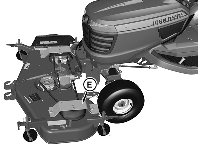
MXT009255-UN-21SEP13 -
NOTE: If rear tires slip, push down on pedal on left side of machine to engage traction assist.
Push top hydraulic lever (A) forward to lower rear draft arms.
-
Drive forward to engage rear draft arms (F) into deck brackets (G), stop once deck begins to be pushed forward.
MXT009256-UN-21SEP13 -
Turn off engine and set the park brake.
-
Check to make sure rear draft lock (H) is in the up position, securing the rear draft arms (F) of the tractor within the rear deck brackets (G). Manually rotate draft lock on deck if necessary to complete the connection.
-
Install front deck hanger (I) through front hooks on deck, then onto the hooks on the vehicle frame. If necessary, manually rotate draft lock from right side of tractor to complete the connection.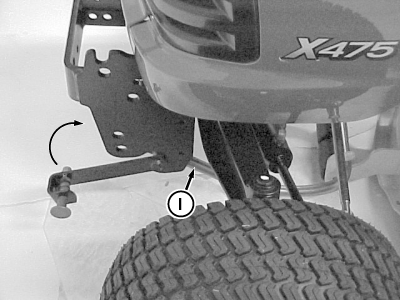
MXT009257-UN-21SEP13 -
Move release latch up (J) and lock pin into hole on frame.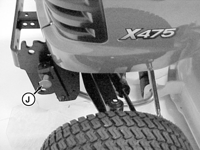
MXT009258-UN-21SEP13 -
NOTE: If auto connect coupler does not line up with gearbox input shaft, see Adjusting Auto Connect Coupler.
If using a standard PTO shaft connection, hook up coupler on deck PTO driveshaft (K) to the stub shaft on the transmission. When coupler locks onto stub shaft, push coupler fully forward and then pull backward to make sure coupler is latched.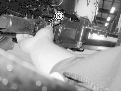
MXT009259-UN-21SEP13 -
Start engine and pull back on top hydraulic lever to raise deck to highest position.
-
Adjust mower height control knob to desired setting.
-
Lower deck by pushing forward on the top hydraulic lever.
-
Turn off engine and set park brake.
-
NOTE: Bottom of anti-scalping wheels should be approximately 6 -13 mm (1/4 - 1/2 in.) from ground.
Turn quick release pin levers (K) to horizontal (open) position. Move anti-scalping wheels to desired operating position, and lower quick release pin levers to lock in place.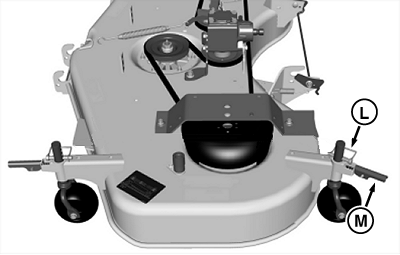
MXT009260-UN-21SEP13 -
Install locking pins (L) in lowest shaft hole above wheel bracket to keep same height setting for later mower installations.
|
BS62576,00014E0-19-20130918 |