Installing Mower (48 and 54 Mower)
-
Park machine safely. (See Parking Safely in the SAFETY section.)
-
Allow engine and muffler to cool completely.
-
 CAUTION: Rotating blades are dangerous. Before adjusting or
servicing mower:
CAUTION: Rotating blades are dangerous. Before adjusting or
servicing mower:- Disconnect spark plug wire(s) or battery negative (-) cable to prevent engine from starting accidently.
- Always wear gloves when handling mower blades or working near blades.
Adjust mower cutting height to lowest position.
-
Slide mower deck under tractor and line up deck bracket (A) with draft arm (B).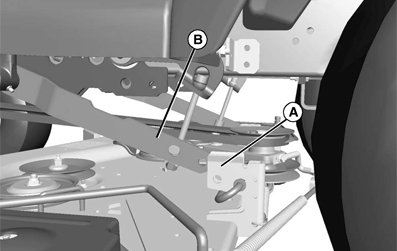
MXAL46039-UN-09APR13 -
Unlock mower lift lock lever.
-
 CAUTION: If the lift pedal is spring-assisted it may have unexpected
movement.
CAUTION: If the lift pedal is spring-assisted it may have unexpected
movement.Lock the lift pedal when installing or removing mower deck.
Pull lift pedal by hand to lower draft arms. Hold pedal securely and lock mower lift lock lever.
-
Install front draft rod (C) into mower bracket (D).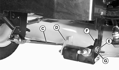
MXAL46040-UN-09APR13If draft rod assembly has been removed from machine:
-
Install mounting stud (E) into draft bracket (F) at each side. Note orientation of stud offset when installing, correct orientation is for stud to be offset above draft rod.
-
Secure each side with locking clip (G).
-
Install draft rod into mower bracket.
-
-
Pull back J-pin (H) and insert through deck bracket (A) and draft arm (B). Make sure pin installs completely through deck bracket. Repeat for other side.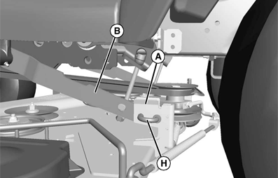
MXAL46041-UN-09APR13 -
 CAUTION: Component is spring-assisted and under tension. Injury
can occur if spring-assisted component is released suddenly.
CAUTION: Component is spring-assisted and under tension. Injury
can occur if spring-assisted component is released suddenly.IMPORTANT: The belt will be damaged if installed wrong. Route the belt properly through belt guides. See belt routing label on mower deck.
MXAL46042-UN-09APR13
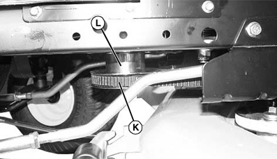
Grasp and hold tension rod (I) securely. Disengage rod from retaining bracket (J) by rotating rod counterclockwise. Move rod as far as possible toward rear wheel. Install separate drive belt (K) onto mower deck and engine sheave (L), and move tension rod back into retaining bracket.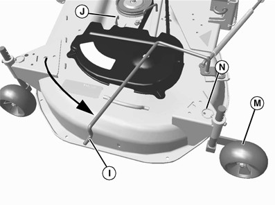
MXAL46043-UN-09APR13 -
Level mower.
-
Raise the deck to cutting height and rotate all mower anti-scalp wheels (M) to operation position:
- Remove locking clip (N) and pin, and move wheel to proper hole position. Install pin and locking clip to secure wheels in position.
|
SP66632,00044BE-19-20130416 |