Install Front Lift Assembly
-
Park machine safely. (See Parking Safely in the SAFETY section.)
-
Raise the tractor lift arms to the highest position.
-
Set Height-of-Cut knob to lowest position.
-
Lower lift arms: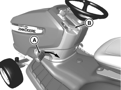
MXT007403-UN-06JUN1344 in with Mechanical Lift:
-
 CAUTION: Avoid injury! Lift pedal is spring-assisted and can
have unexpected movement. Lock lift pedal when installing or removing
attachment.
CAUTION: Avoid injury! Lift pedal is spring-assisted and can
have unexpected movement. Lock lift pedal when installing or removing
attachment.Pull lift pedal (A) back by hand to lower linkage to the lower/down position.
-
Pull lock lever (B) up to lock linkage in the lowered position.
44 in and 47 in with Hydraulic Lift:
a. Push down on the lift lever (C).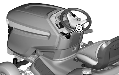
MXT013992-UN-18JUN15 -
-
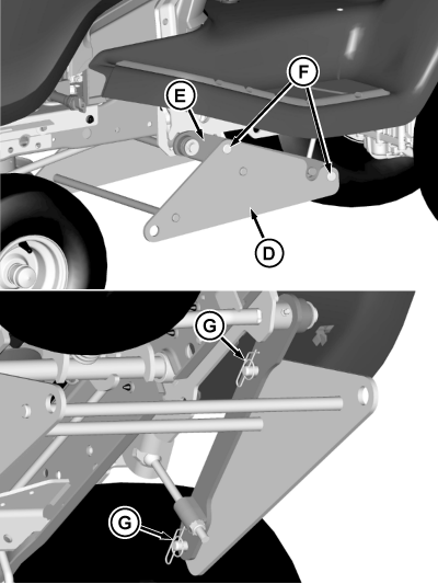
MXT013976-UN-16JUN15Picture Note: Rear lift bracket to left-hand lift arm shown.
D - Bracket, Rear Lift
E - Lift Arm
F - Weld Pins
G - Cotter Pin, Self-Locking
Install rear lift bracket:-
Install bracket (D) onto the left-hand lift arm (E) by inserting the weld pins (F) into the holes on the lift arm.
-
Install self-locking cotter pins (G).
-
MXT013977-UN-16JUN15Picture Note: Rear lift bracket to right-hand lift arm shown.
H - Holes
I - Bracket, Rear Lift
J - Lift Arm
K - Pin, Clevis
L - Cotter Pin, Self-Locking
Align holes (H) on bracket (I) with the holes on the right-hand lift arm (J). -
Insert pins (K) through the lift arm and bracket.
-
Install self-locking cotter pins (L).
-
-
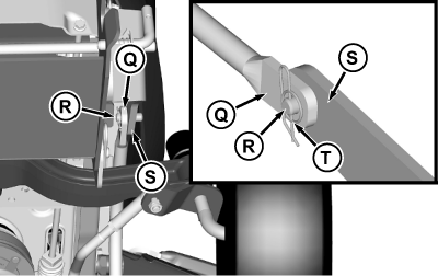
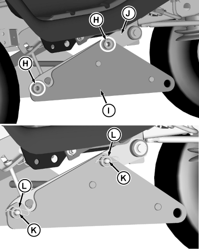
MXT013979-UN-16JUN15Picture Note: Lift link to left side of hitch shown.
Q - Flattened End
R - Weld Pin
S - Hitch, Front Attachment
T - Cotter Pin, Self-Locking
Assemble lift links:-
Install flattened end (Q) of the lift link onto the weld pin (R) inside the hitch (S).
-
Install self-locking cotter pin (T).
-
Repeat steps a and b to install second lift link onto the other side of the hitch.
-
-
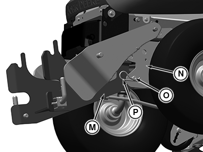
APY15563-UN-26JUL19M - Hitch, Front Attachment
N - Front Draft Assembly
O - Pin, Front Draft
P - Spring Locking Pin, 4.5 mm
Align hole in hitch (M) with the hole in front draft assembly (N). -
Install 300 mm (11.8 in) pin (O) and large spring locking pin (P).
-
Install lift links:
-
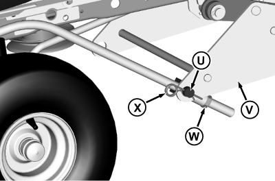
MXT013980-UN-07AUG15U - Swivel Boss
V - Bracket, Rear Lift
W - Locknut
X - Spring Locking Pin, 3.72 mm
Pivot front hitch up until swivel boss (U) aligns with the hole in bracket (V). -
Insert swivel boss into the hole and install spring locking pin (X).
-
Repeat steps a and b to finish installation of second lift link.
-
Adjust lock nut (W) if necessary.
-
|
MG39705,00001E0-19-20190726 |