Install Snowblower
-
IMPORTANT: Avoid damage! Both the auger gear box and the snowblower drive gear box oil levels must be checked, and oil added if necessary, before installation. This procedure must be performed with the snowblower removed from the machine. See “Checking Gearbox Oil” in the SERVICE section for details.
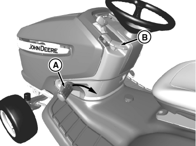
MXT007403-UN-06JUN13A - Lift Pedal
B - Lock Lever
Lower attachment linkage:44 in Models with Mechanical Lift System
-
 CAUTION: Avoid injury! Lift pedal is spring-assisted and can
have unexpected movement. Lock lift pedal when installing or removing
attachment.
CAUTION: Avoid injury! Lift pedal is spring-assisted and can
have unexpected movement. Lock lift pedal when installing or removing
attachment.Pull lift pedal (A) back by hand to lower linkage to the lower/down position.
-
Pull lock lever (B) up to lock linkage in the lowered position.
44 in and 47 in Models with Hydraulic Lift System
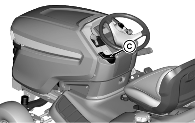
MXT013992-UN-18JUN15C - Lift Lever
a. Push down on the lift lever (C). -
-
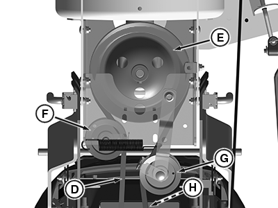
APY15561-UN-26JUL19Bottom view
D - Drive Belt
E - Gearbox Drive Sheave
F - Idler Sheave
G - Tensioning Sheave
H - Machine Drive Sheave
Check snowblower drive belt (D) for wear and proper routing:- Belt is routed around the gear box drive sheave (E), inside belt guards on idler sheave (F) and tensioning sheave (G), then to the machine drive sheave (H).
- The tensioning spring connects to the tensioning sheave pivot arm, under the sheave.
- Belt must be installed on the gear box drive sheave from below, if it requires replacement.
-
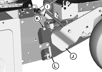
MXT013981-UN-16JUN15I - Blower Support
J - Hitch, Front Attachment
K - Support Pins
L - Spring-Loaded Pins
Align blower support (I) with the front attachment hitch (J). -
Install blower support pins (K) into top slots in the front attachment hitch.
-
Pull spring-loaded pins (L), on each side, outward and lower blower support bracket. Release spring-loaded pins and lock blower support in place.
-
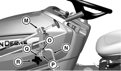
MXT007362-UN-29MAY13M - Chute and Spout Bracket
N - Rotation Handle Wireform
O - Carriage Bolt, M8 x 20
P - Washer, M8.4
Q - Lockwasher
R - Knob
Align the slot at the bottom of the chute and discharge spout bracket (M) over the locating screw at the outside of the rotation handle bracket (N). -
Insert carriage bolt (O), from the inside, through the square mounting hole in the rotation handle bracket (N). Continue through the mounting hole at the bottom of chute and discharge spout bracket (M). Secure with an M8.4 washer (P), 3/8 in lockwasher (Q), and knob (R).
-
CAUTION: Avoid injury! Attachment can lower rapidly. Attachment
is heavy and can crush.
Keep bystanders, especially children, away when lowering attachment.
Support raised attachment with a mechanical stop or lower completely to the ground before servicing.
Install drive belt on the machine drive sheave:
-
Raise and block-up the snowblower.
-
To remove tension on the belt, pull or push the spring-loaded tensioning sheave arm.
-
Install belt on the machine drive sheave (PTO clutch).
-
Release tensioning sheave arm.
-
Raise snowblower, remove support, and lower snowblower to ground.
-
-
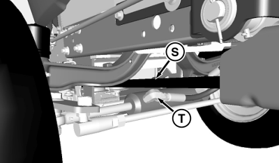
MXT007363-UN-29MAY13S - Drive Belt
T - Steering Cylinder Fitting
Check for interference between the drive belt (S) and the left side fitting (T) on the machine steering cylinder. If necessary, rotate fitting down approximately 10° to eliminate interference and premature belt wear. -
Raise snowblower fully to test lift adjustment:
Models with Mechanical Lift System
- To unlock the latch, pull up slightly on the foot pedal (A) and push down on the lock lever (B). To lock blower in raised position, push foot pedal all the way down and lift lock lever. The snowblower must be approximately 12.7 cm (5 in) off the ground when in fully raised position.
- If the snowblower does not lock in the raised position, adjust lift height down and recheck.
Models with Hydraulic Lift System
- Start engine and pull up on lift lever (C) to raise the snowblower. The snowblower must be approximately 12.7 cm (5 in) off the ground when in the fully raised position.
- Adjust lift height if necessary and check for any binding of lift linkage.
|
MG39705,00001E1-19-20190626 |