Removing Blade
 CAUTION: Avoid injury! When the attachment is removed, also
remove any ballast that was added to the machine.
Use only attachments and accessories recommended by the manufacturer.
-
Park machine safely. (See Parking Safely in Safety section.)
-
Raise blade.
-
 CAUTION: Avoid injury! Attachment is heavy and can crush.
Keep hands and arms from under attachment when in the raised position.
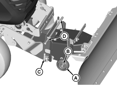
Remove gauge wheels (A) from storage position and install one on each side of blade frame. Fasten with spring locking pin (B).
MXT014757-UN-18JUN15 -
Put blocks or a board under blade.
-
Lower blade onto blocks or board.
-
To remove just the blade, pull out spring-loaded pins (C) on each side. Pull blade assembly up to disengage two pins (D) from slots at top of hitch.
-
Make sure that the lift arms are lowered all the way down.
-
NOTE: Reinstall hardware onto lift components for storage.

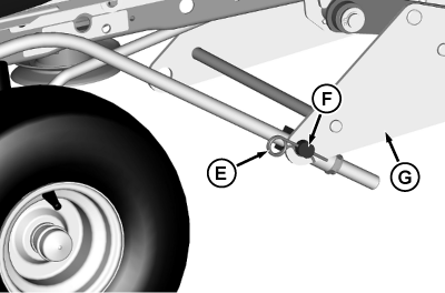
MXT014758-UN-18JUN15E - Spring Locking Pin, 3.72 mm
F - Swivel Bosses
G - Bracket, Rear Lift
Remove the lift links:-
Remove spring locking pins (E) that attach the swivel bosses (F) onto bracket (G).
-
Disengage the lift links from the rear lift bracket.
-

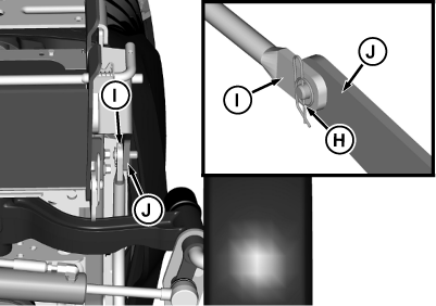
MXT014759-UN-18JUN15H - Cotter Pin, Self-Locking
I - Lift Link
J - Hitch, Front Attachment
Remove self-locking cotter pins (H) that attach the lift links (I) to the hitch (J). -
Set the lift link assemblies aside.
-
-

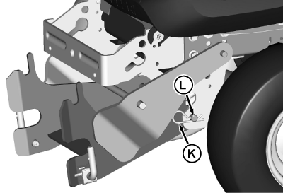
MXT014760-UN-18JUN15K - Spring Locking Pin, 4.5 mm
L - Pin, Front Draft
Remove the hitch:-
NOTE: Install front draft pin and spring locking pin in front hitch assembly for storage.
Remove spring locking pin (K) and pin (L).
-
Set the front hitch aside.
-
-

MXT014761-UN-18JUN15Picture Note: Top image is left side, bottom image is right side.
M - Cotter Pin, Self-Locking
N - Bracket, Rear Lift
O - Pin, Clevis
Remove rear lift bracket:-
Remove self-locking cotter pins (M) attaching bracket (N) to the lift arms.
-
While supporting the rear lift bracket from the bottom, remove pins (O) attaching bracket to right-hand lift arm.
-
Remove the rear lift bracket from the left-hand lift arm.
-
Reinstall the two free pins and four self-locking cotter pins onto the rear lift bracket for storage.
-
|
OUMX068,0000C31-19-20150922 |