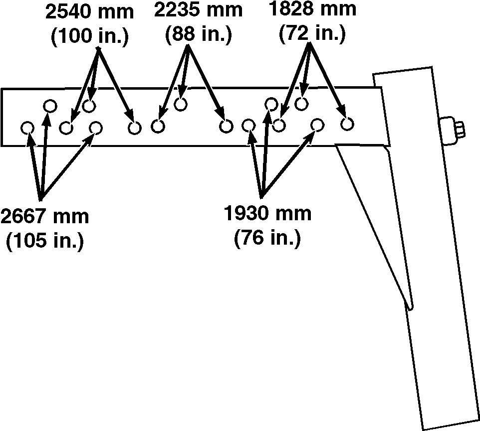
Adjusting Front Wheel Tread-1829-2667 mm (72-105 In.) Wheel Spacing (If Equipped)1. Using chart, find specific row spacing of field and read across to wheel tread setting.
NOTE: Tread measurement taken between centerlines of each tire, at the front, near the ground.
IMPORTANT: Do not place jack under solution pump cover or machine damage will occur. 2. Raise one side of machine so wheel is off the ground. |
AG,OUO1011,280 -19-27APR99-1/2 |
|
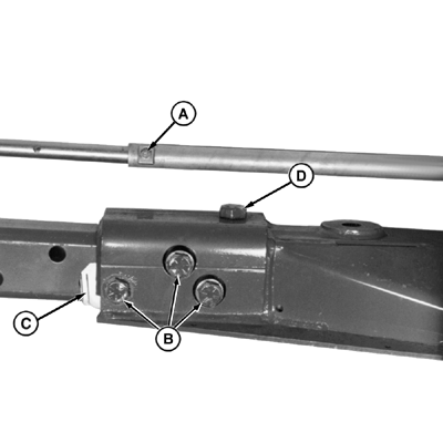
3. Remove tie rod locating bolt (A). 4. Using wrench N203235 (provided), remove axle bolts (B) and shims (C). 5. Remove cap screw (D) and nut. 6. Reposition axle end and tie rod to holes that agree with desired tread width. See hole/width diagram. IMPORTANT: Machine damage can occur if axle bolts (B) and cap screw (D) and nut are not tightened to the proper specification. 7. Loosely install hardware in their original positions. Tighten hardware to specification. Specification
8. Install tie rod locating bolt. 9. Repeat entire procedure on opposite side. 10. Check toe-in and adjust, if necessary. (See CHECKING FRONT AXLE TOE-IN [4-WHEEL] and ADJUSTING FRONT AXLE TOE-IN [4-WHEEL] in this section
|
|
AG,OUO1011,280 -19-27APR99-2/2 |
 CAUTION:
Machine is heavy. Be sure to use jack or hoist which is large enough to raise machine safely.

