Adjusting Rear Wheel Tread-Hydraulic Adjust 2006-3073 mm (79-121 In.) Wheel Spacing (If Equipped)
NOTE: Rear wheel tread setting is infinitely adjustable between 2006-3073 mm (79-121 in.). Refer to chart for row spacing-to-tread setting recommendations. 1. Find the specific row spacings of the field in the chart. Read across to the recommended wheel tread.
|
AG,OUO1011,282 -19-27APR99-1/8 |
|
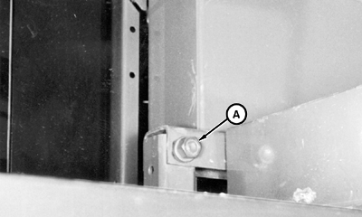
2. Loosen lift arm crossbrace hardware (A).
|
|
AG,OUO1011,282 -19-27APR99-2/8 |
|
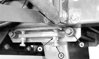
3. Using wrench N203235 (provided), loosen cap screws (B) with jam nuts (A) so frame rides on rollers (C).
|
|
AG,OUO1011,282 -19-27APR99-3/8 |
|
4. When extending axles out, move tie bolts (E) to holes that most closely agree with desired tread width. When retracting axles, move tie bolts to inner position after adjustment is made. Leave tie bolts snug during adjustment.
|
|
AG,OUO1011,282 -19-27APR99-4/8 |
|
NOTE: Visual indicators (A) at the rear of each step show rear tread width. Observe indicators while making tread width adjustments. 5. Start engine and drive forward 2-5 Km/h (1-3 mph). IMPORTANT: DO NOT attempt to adjust both axles at the same time or exceed 2-5 Km/h (1-3 mph). Operate one switch until axle is completely extended/retracted and then adjust axle on opposite side.
|
|
AG,OUO1011,282 -19-27APR99-5/8 |
|
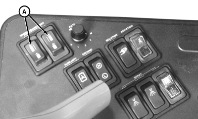
6. While moving forward, depress one wheel adjustment switch (A), until tread indicator shows desired width and drop axle contacts tie bolts; and then second switch to adjust opposite side axle. 7. Stop machine and shut off engine.
|
|
AG,OUO1011,282 -19-27APR99-6/8 |
|
8. Tighten cap screws (B) to specification, to lift frame from rollers (C). Tighten jam nuts (A). Specification
|
|
AG,OUO1011,282 -19-27APR99-7/8 |
|
9. Tighten lift arm crossbrace hardware (A). 10. Tighten tie bolts to specification. Specification
|
|
AG,OUO1011,282 -19-27APR99-8/8 |
 CAUTION:
Do not modify machine to achieve a tread setting of less than 2006 mm (79 in.). Machine will be unstable and can tip, causing serious injury or death to you or others.


