Adjusting Rear Wheel Tread-Manual Adjust 1829-2667 mm (72-105 In.) Wheel Spacing (If Equipped)
NOTE: Sprayer with narrow tread option is infinitely adjustable between 1829-2896 mm (72-114 in.). Refer to chart for row spacing-to-tread setting recommendations. 1. Using chart, find specific row spacing of field and read across to wheel tread setting. Rear tread setting should agree with front wheel positions.
|
AG,OUO1011,283 -19-27APR99-1/7 |
|
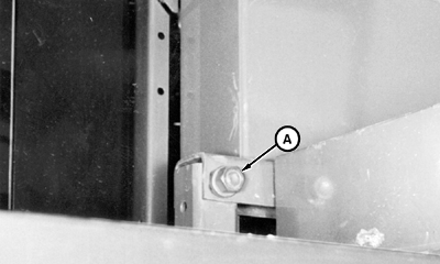
2. Loosen lift arm crossbrace hardware (A).
|
|
AG,OUO1011,283 -19-27APR99-2/7 |
|
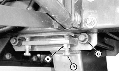
3. Using wrench N203235 (provided), loosen cap screws (B) with jam nuts (A) so frame rides on rollers (C).
|
|
AG,OUO1011,283 -19-27APR99-3/7 |
|
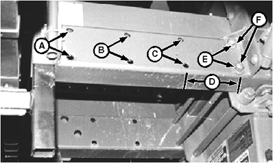
4. When extending axles out, move tie bolts (F) to holes that most closely agree with desired tread width. Use adjustment area (D) for 1930 mm (76 in.) tread setting (see note). When retracting axles, move tie bolts to inner position after adjustment is made. Leave tie bolts snug during adjustment. NOTE: No holes are provided for 1930 mm (76 in.) tread setting. When this setting is needed, move drop into adjustment area (D), placing rear wheel in alignment with front tire.
5. Raise one rear wheel off the ground using a suitable rolling floor jack or hoist. |
|
AG,OUO1011,283 -19-27APR99-4/7 |
|
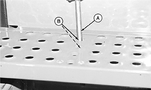
6. Slide tapered end of tread adjustment wrench (A) through reinforced holes (B) in step and drop axle. Pry drop axle out to contact tie bolts.
|
|
AG,OUO1011,283 -19-27APR99-5/7 |
|
7. Tighten cap screws (B) to specification to lift frame from rollers (C). Tighten jam nuts (A). Specification
|
|
AG,OUO1011,283 -19-27APR99-6/7 |
|
8. Tighten lift arm crossbrace hardware (A). 9. Lower wheel to the ground. 10. Repeat entire procedure on opposite side. 11. Tighten tie bolts to specification. Specification
|
|
AG,OUO1011,283 -19-27APR99-7/7 |
 CAUTION:
Do not modify machine to achieve a tread setting of less than 1829 mm (72 in.). Machine will be unstable and can tip, causing injury or death to you or someone else.


