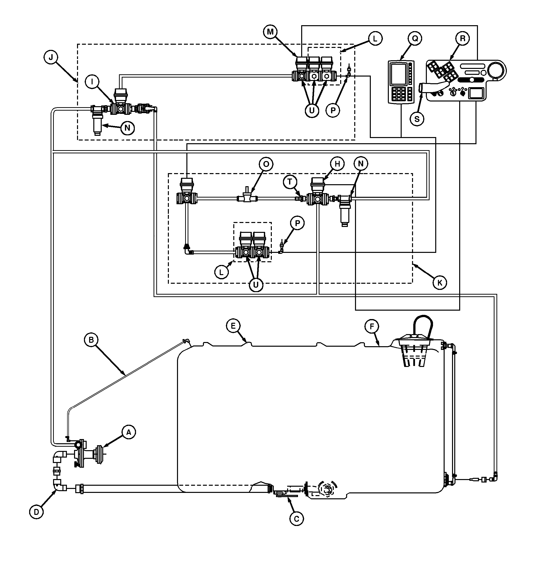
Solution Spray System Operation-V-Tank

|
AG,OUO1011,341 -19-28APR99-1/3 |
|
|
|
|
|
SYSTEM COMPONENTS: The solution spray system consists of a tank, centrifugal pump, strainer, solution control valve, boom section shut-off valves and spray nozzles mounted on the booms. The solution tank is made from polyethylene. The capacity of the V-Tank is 1590 L (420 gal) and the capacity of the T-Tank is 1552 L (410 gal). A filler cap is located at the top rear of the tank. A bucket type fill strainer is located inside the filler cap opening. The strainer prevents trash from entering the tank and can be used to dissolve and mix chemicals with water when filling tank. An optional quick-fill attachment can be installed for faster filling. At the rear of the tank, a clear tube and graduated scale indicate solution level in liters and gallons. At the bottom of the tank are the cleanout/drain plug, shut-off valve and solution outlet. If the electric agitation control configuration is installed, agitation is turned on and off using a console mounted switch and an electric agitation valve located on the boom. The valve is open or closed to control agitation flow by setting the agitation level using the SPRAYSTAR ™ monitor. If the manual agitation control configuration is installed, agitation is turned on and off using a manual shut-off valve located at the rear of the sprayer. The valve can be opened and closed to control agitation flow and attain desired effect. Agitation flow enters both tanks through a connection at the rear of the tanks. For the V-Tank, solution |
enters the tank through an agitator jet. For the T-Tank, solution enters the tank through a sparge tube which runs the length of the tank to assure uniform chemical mixture.
The centrifugal pump is driven by a V-belt directly from the engine crankshaft. A magnetic clutch located at the sheave end of the pump provides the means of engaging and disengaging the pump through operation of a switch located on the operator's side control console. Air trapped in the pump is allowed to escape through bleed-off line. This helps prevent pump cavitation. The non-corrosive strainer is located at the center boom section. It can be cleaned by removing the end cap. The flowmeter is located between the strainer and the solution control valve. It converts the solution flow rate to a frequency, which is used by the SPRAYSTAR ™ spray rate control system in controlling solution flow. The flowmeter can be easily cleaned by removing the turbine assembly and rinsing. The solution control valve is a motorized ball valve that regulates the solution pressure and flow to the spray nozzles. It is controlled by the SPRAYSTAR ™ spray rate control system. A pressure transducer is located at the end of the boom section shut-off valve manifold. The transducer converts the solution pressure to a voltage signal that is sent to SPRAYSTAR ™ spray rate control system. |
|
SPRAYSTAR is a trademark of Deere & Company. | AG,OUO1011,341 -19-28APR99-2/3 |
|
The boom section shut-off valves are motorized ball valves that cycle completely open or completely closed. The valves are operated by switches located on the operator's side control console and the hydro lever. An optional third valve may be added to split the spray among the center frame and right and left booms. The spray nozzles, located on the center frame and booms, meter, atomize and dispense the solution into specific patterns. Solution flow is metered by the size of the orifice in the nozzle tip. Within limits, solution flow through a nozzle can be increased or decreased by adjusting solution pressure. Most nozzles are designed for optimum performance at specific pressures. However, the range of adjustment is relatively narrow. Line pressures which are too high or too low will affect atomizing the solution and create variations in spray pattern. The solution atomizes when the liquid is forced through the orifice in the nozzle. |
The shape of the spray pattern is determined by the shape of the orifice.
SYSTEM OPERATION: When the pump is activated, solution is drawn from the solution tank, through the suction line. The pump pushes the solution out to the strainer. On machines with V-Tank, part of the solution flow returns to the tank through the agitation line and agitator jet. On machines with T-Tank, part of the solution flow returns to the tank through the agitator line and sparge tube. The balance of the solution flows to the solution control valve, which limits the amount of solution reaching the boom section shut-off valves. When the boom section shut-off valves are open, the solution flows to the nozzles, where it is atomized and sprayed. |
AG,OUO1011,341 -19-28APR99-3/3 |