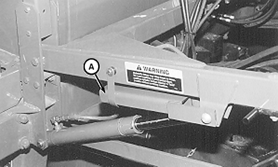
Attaching BoomNOTE: Front fold boom attachment, as described here, is performed with boom sections unfolded. 1. Move lift cylinder lockup (A) to storage position.
|
|
AG,OUO1011,371 -19-29APR99-1/7 |
|
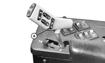
2. Start engine and lower lift arms using raise/lower switch (A). Shut off engine.
|
|
AG,OUO1011,371 -19-29APR99-2/7 |
|
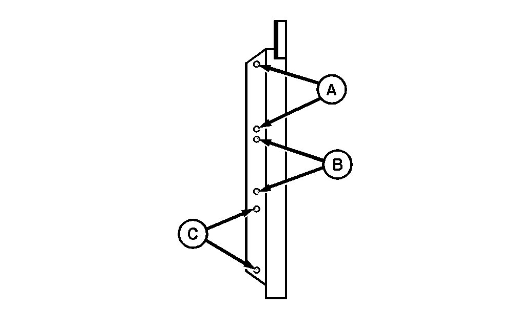
NOTE: Three height ranges are available on front folding boom. Attach lift and stabilizer arms at center frame holes A, B, or C, to obtain desired height range.
|
|
AG,OUO1011,371 -19-29APR99-3/7 |
|
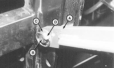
3. Raise boom and attach stabilizer arms (A) to center frame using 7/8 x 3-3/4 in. round head pins (B), with 0.060 x 0.906 x 1.50 in. flat washers (C) and 5/16 in. quick-lock pins (D) to the inside.
|
|
AG,OUO1011,371 -19-29APR99-4/7 |
|
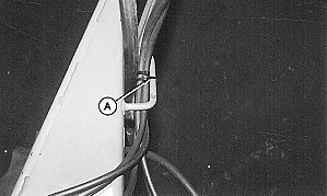
4. Route hydraulic hoses through hose holders on lift arms. Retain hoses with tie straps (A).
|
|
AG,OUO1011,371 -19-29APR99-5/7 |
|
NOTE: To help identify and properly connect hoses, (AR103808) Hose Identification Kit is available from your John Deere dealer.
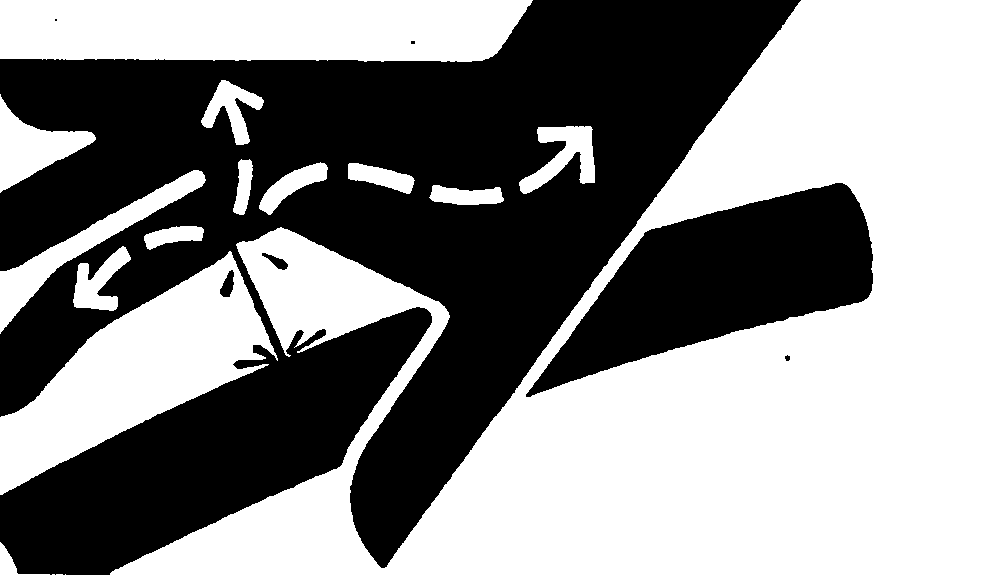
If an accident occurs, see a doctor immediately. Any fluid injected into the skin must be surgically removed within a few hours or gangrene may result. Doctors unfamiliar with this type of injury should reference a knowledgeable medical source. Such information is available from Deere & Company Medical Department in Moline, Illinois, U.S.A.
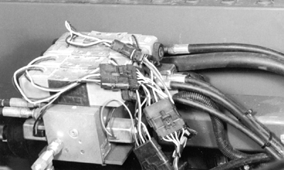
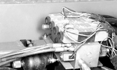
5. Remove caps from port connectors and attach hoses to "FOLD", "UNFOLD", "LEVEL PISTON", and "LEVEL ROD" ports. Refer to Hydraulic Hose Diagram in this section for correct hose-to-valve port connections. |
|
AG,OUO1011,371 -19-29APR99-6/7 |
|
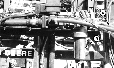
6. Route solution hose through hose holders on lift arms. Attach hose (A) to solution strainer (B).
|
|
AG,OUO1011,371 -19-29APR99-7/7 |
 CAUTION:
Boom is heavy and can fall causing serious injury or death to you or others. Use lifting equipment which is large enough to raise boom safely.
