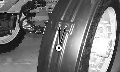
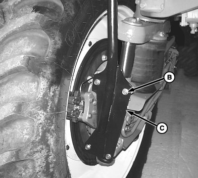
Install Optional TiresNOTE: Before jacking a front wheel, turn it fully outward. Retain fender mounting hardware for installation of jack plate. 1. Remove cap screws (A), cap screws (B), fender mount bracket (C), and fender.
|
|
OUO6092,00004D3 -19-31AUG04-1/4 |
|
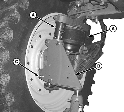
NOTE: JDG1781 Spindle Spacers are available from your John Deere dealer. 2. Inflate air spring and install JDG1781 Spindle Spacer (A) on each spindle. 3. Deflate air spring until machine is resting on spacers. 4. Position jack plate (B) and install cap screws (C). 5. Raise machine using bottle jack at location shown. IMPORTANT: Support machine using stands with a minimum capacity of 3628 kg (8000 lb). 6. Support machine using suitable stands. |
|
 CAUTION:
Air spring can explode if over inflated causing serious injury or death to you or others. When adjusting suspension assemblies, do not exceed 689 kPa (6.89 bar) (100 psi). Keep hands and body away from suspension linkage.
CAUTION:
Air spring can explode if over inflated causing serious injury or death to you or others. When adjusting suspension assemblies, do not exceed 689 kPa (6.89 bar) (100 psi). Keep hands and body away from suspension linkage.
OUO6092,00004D3 -19-31AUG04-2/4 |
|
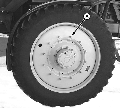
IMPORTANT: Approximate weight of outer wheel and tire assembly is 340 kg (750 lb). 7. Attach suitable lifting device to outer wheel and tire assembly. 8. Remove nuts (A), spacers, and outer wheel and tire assembly. IMPORTANT: To avoid machine damage from improperly tightened wheel hardware, always lubricate wheel bolts with SAE 30W oil prior to installing wheel nuts. IMPORTANT: Damage to planetary hub and wheel can occur if the correct mounting nut torque is not maintained. Tighten nuts in a crisscross pattern to specification. Tighten wheel mounting nuts after first 1 hour of use and every 10 hours thereafter until correct torque is maintained. Check wheel nuts torque after every 100 hours of use. 9. Lubricate mounting studs with clean oil and install outer wheel and tire assembly, spacers, and mounting nuts. 10. Raise machine and remove support stands. 11. Lower machine and remove jack plate. 12. Inflate air spring and remove JDG1781 Spindle spacers. 13. Tighten wheel mounting nuts (A) in a crisscross pattern to specification. Specification
14. Install fender in reverse order using the following special instructions:
|
|
OUO6092,00004D3 -19-31AUG04-3/4 |
|
Specification
Repeat procedure for remaining tires. Adjust air springs as necessary. (See Adjust Front And Rear Air Spring Assemblies in Chassis section.) |
|
OUO6092,00004D3 -19-31AUG04-4/4 |