Attaching Machine To Tractor
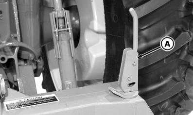
IMPORTANT: Machine can attach to Category 3, 4N and semi-integral couplers. Do not use Category 3N or damage to machine may occur. 1. Pull up on coupler latch levers (A). 2. Lower hitch until quick coupler hooks are lower than implement hitch pins. 3. Back tractor up to machine. |
|
 CAUTION:
To avoid serious injury or death to you or others:
CAUTION:
To avoid serious injury or death to you or others:
OUO6061,000290A -19-04APR08-1/7 |
|
4.
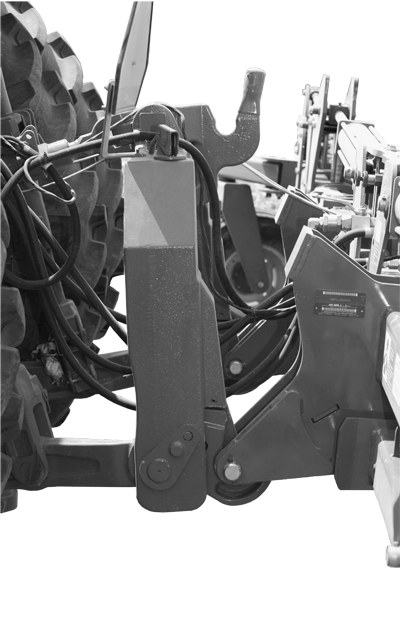
Raise hitch enough to engage machine pins on hooks.
5. Push coupler latch levers down to lock machine to quick coupler. |
|
OUO6061,000290A -19-04APR08-2/7 |
|
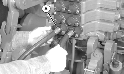
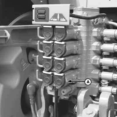
IMPORTANT: Be sure to correctly connect hoses to couplers. If hose connections are reversed, machine will not respond to electronic controls (if equipped). 6. Push green tie band wing-fold hoses (A) in SCV I couplers. Pressure hose attaches to LEFT coupler. 7. Push yellow band fertilizer opener hoses into SCV II couplers. Pressure hose attaches to LEFT coupler.
|
|
OUO6061,000290A -19-04APR08-3/7 |
|
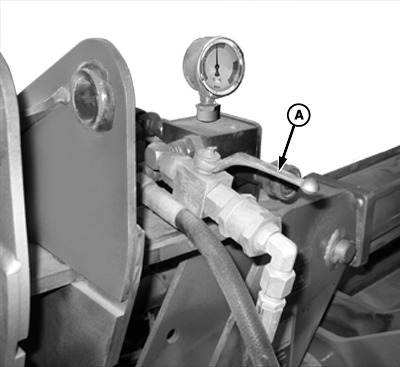
8. For field operation, OPEN transport lock-up valve by turning handle (A) in-line with valve. |
|
OUO6061,000290A -19-04APR08-4/7 |
|
9.
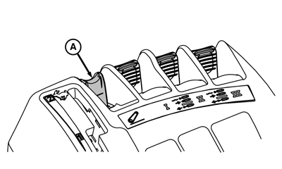
Slowly pull hitch control lever (A) to raise machine just above ground.
|
|
OUO6061,000290A -19-04APR08-5/7 |
|
10.
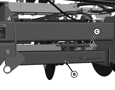
Pull pin (A) and set parking stand in transport position (B) using pin and lock pin (C). Repeat on other side.
|
|

OUO6061,000290A -19-04APR08-6/7 |
|
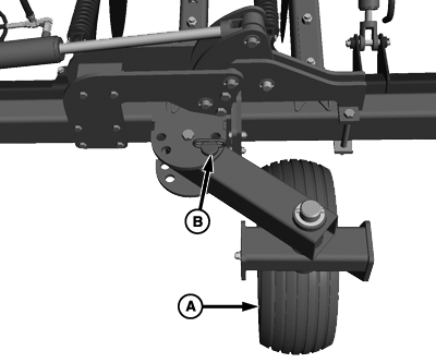
IMPORTANT: Stabilizer wheel MUST be set correct location hole or damage to machine may occur during transportation. NOTE: Refer to ADJUST STABILIZER WHEEL in Operating Machine section for using stabilizers correctly in field. 11. Set stabilizer wheel (A) to transport position (B) by pulling lock pin and pin. 12. Align stabilizer wheel arm to transport position hole. 13. Lock wheel arm using pin and lock pin. 14. Repeat process on other side. 15. Lower machine to ground.
|
|
OUO6061,000290A -19-04APR08-7/7 |