Repairing Module Builder Forming Belts
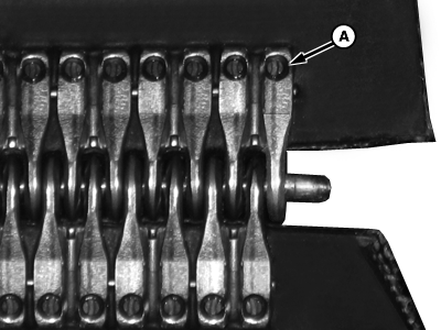
N88314-UN-06APR10Rivet Head (Pulley Side of Belt)
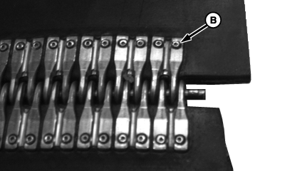
N88313-UN-06APR10Rivet Head (Module Side of Belt)
A - Rivet Head (Pulley Side
B - Rivet Head (Module Side)
Remove broken belt.Before cutting damaged areas or laces from belt, identify and mark pulley side of belt. The pulley side of the belt has the most contact with the rollers and no contact with the module. The pulley side is identified by the shape of rivet head (A) on the lacing. The lace rivet on the pulley side of the belt has a circular split in it. The lace rivet head (B) on the side of the belt that contacts the module has a circular dimple in it.
E40026-UN-30MAY96
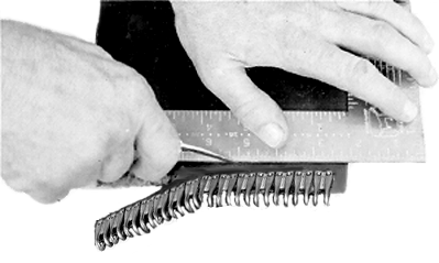
Remove damaged area using a square and a sharp knife. Check to be sure that belt end was cut squarely.
E21798-UN-24JUN99NOTE: If belts are shorter than the specified dimensions, a short piece of belt can be added. Splices (on same belt) must be at least 305 mm (12 in.) apart.
Check belt length. Make sure that belt is neither longer nor shorter than specified.
7760 RMB Belt Lengths
Minimum
Repair
Maximum
Narrow Belts
18 057 mm (710-7/8 in.)
18 082 mm (711-7/8 in.)
18 107 mm (712-7/8 in.)
Wide Belts
18 210 mm (717 in.)
18 235 mm (718 in.)
18 260 mm (719 in.)
IMPORTANT: Trailing end of belt must be trimmed using dimensions shown in illustration. DO NOT vary from these dimensions.
NOTE: Arrow shown in illustration indicates direction of belt travel.
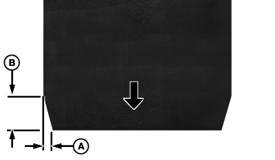
N88351-UN-12APR10A - Dimension, 6 mm (0.25 in.)
B - Dimension, 19 mm (0.75 in.)
Trim trailing end of belt as shown.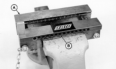
E40773-UN-08AUG96A - Lacing Tool
B - Holes
Position belt lacing tool (A) in vise with holes (B) toward operator and shoulder of tool resting on jaws of vise.IMPORTANT: Use only 17 lace segments on wide belts and 14 segments on narrow belts. Using more or less segments can result in premature lace failure.
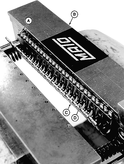
E40774-UN-08AUG96A - Rivet Pins
B - Lacing Tool
C - Lacing Strip
D - Stop Pins
Install lacing strip (C) in lacing tool (B). Make sure that two rivet pins (A) on each lacing segment are inserted into each of the 17 holes in tool for the wide belt or 14 of the 17 holes for the narrow belt. Lacing segments must rest against stop pins (D).Tighten vise until lacing strip is lightly gripped and belt can be easily inserted.
IMPORTANT: When belts are connected, edges must be aligned to prevent belt damage.
NOTE: Arrows shown in illustrations indicate direction of belt travel as it corresponds to square and tapered ends of belt.
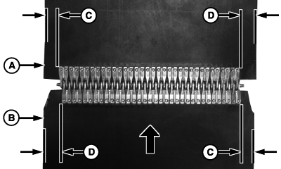
N88312-UN-12APR10Wide Belt Lacing Offsets
N88311-UN-12APR10Narrow Belt Lacing Offsets
A - Belt Edge (Leading End)
B - Belt Edge (Trailing End)
C - Dimension, 16 mm
D - Dimension, 19 mm
E - Dimension, 11 mm
F - Dimension, 14 mm
Laces use the same number of segments on each end of belt. To keep belt edges aligned when belt is connected, laces must be offset slightly as shown. The belt expands when laces are installed. Mark offsets and adjust position of belt in lacing tool as necessary.
E40775-UN-08AUG96
E40776-UN-08AUG96A - Stop Plate
B - Belt
C - Hand Punch
D - Pneumatic Hammer
Install belt (B) in lacing strip with pulley side of belt toward operator. While holding edge of belt against stop plate (A), uniformly push belt down to the stop pins. Make sure that lacing strip is against stop pins.Make sure that belt and lacing are positioned squarely in lacing tool. Close vise on belt and lacing until distance between lacing tool jaws equals width of belt.
IMPORTANT: If using a hand punch, using too large of a hammer or striking punch too hard can damage lacing tool or belt lacing.
If using pneumatic hammer, too high air pressure and/or too long riveting time can damage lacing tool or belt lacing.
Drive rivets through belt using a punch (C) or pneumatic hammer (D).
Rivet the two outer lacing segments first, then working from the outside to the inside, rivet remaining lacing segments.
- If using punch (C), drive rivets until shoulder on punch shaft contacts lacing tool jaw. Hit punch an additional time to ensure contact between shoulder and jaw.
- If using pneumatic hammer (D), set air pressure to 500—600 kPa (5—6 bar) (72—87 psi). Operate hammer for 1—2 seconds for each rivet. Re-riveting is usually not necessary.
Remove belt from vise and inspect lacing. All rivets must be driven through belt and show punch marks in center of rivets.
IMPORTANT: Do not hit loop area of fastener when using hammer to flatten heads of rivets.
Do not hit rivets too hard or rivets can buckle and damage joints.
E40027-UN-30MAY96Flatten Rivets
Put belt and lacing on a solid base. Flatten heads of rivets using the flat face of a small hammer. Strike several rivets at a time using a light tapping motion. Rivets must be flush with splice.Repeat procedure for other end of belt.
IMPORTANT: Belt must be installed so that square cornered end leads as belt moves in normal direction of travel.
Install belt in module builder. (See BELT ROUTING AND ROLL DIAGRAM in this section.) Square cornered end of belt must lead the end with trimmed corners as belt moves in normal direction of travel.
Connect belt ends and check alignment of belt edges approximately 51 mm (2 in.) back from end of belt.
DP99999,0000572-19-20100412 |