Replacing Module Builder Belts
N88293-UN-30MAR10
N87330-UN-17NOV09
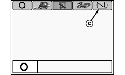
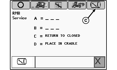
Mode Selection Menu
N88294-UN-30MAR10
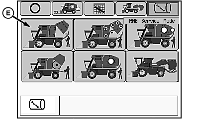
RMB Service Mode Menu

N88030-UN-02MAR10
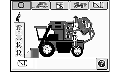
Service Setup Functional Diagram
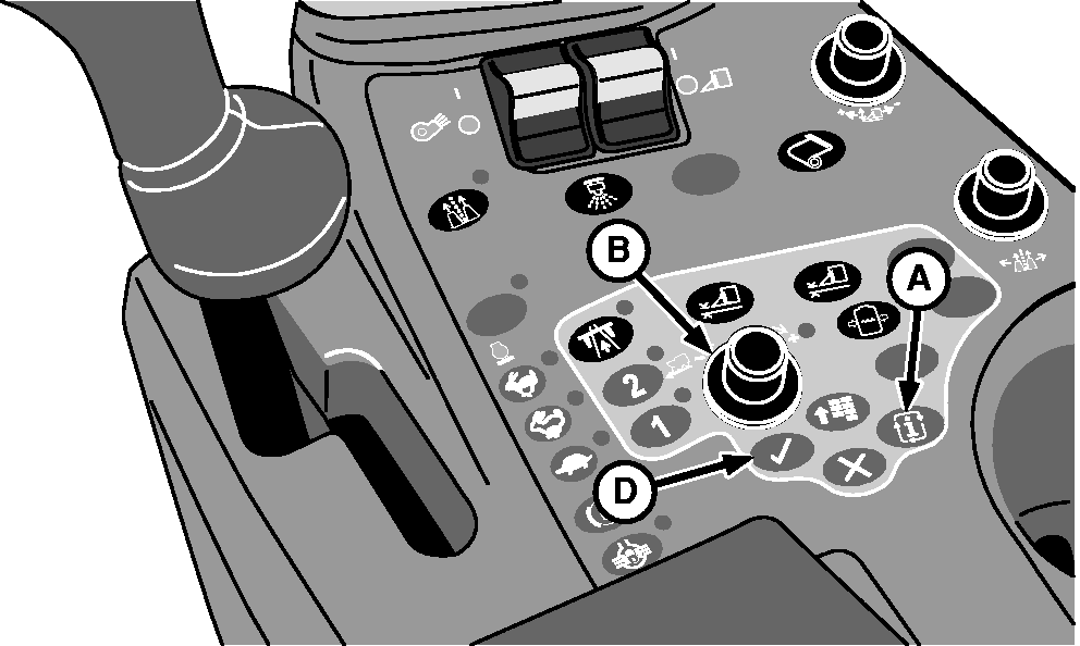
A - Mode Select Button
B - Selection Dial
C - RMB Service Mode Tab
D - Confirm Button
E - RMB Service Setup Mode Icon
There are a total of 11 module forming belts. Belts are individually repaired or replaced as required. (For repair information, see REPAIRING MODULE BUILDER FORMING BELTS in this section.)
Before beginning belt replacement, park machine on a flat, level surface with sufficient room behind machine to lay belt out on ground.
-
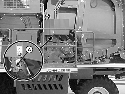
Remove tether control unit from storage bracket on front of power module.
-
Start engine and wait for controllers and armrest display unit to initialize.
-
IMPORTANT: Round module builder (RMB) must be locked down to activate this service mode.
Press mode select button (A). Mode selection menu appears.
-
Rotate selection dial (B) to highlight RMB service mode tab (C).
-
Press confirm button (D). RMB service mode menu appears.
-
Highlight RMB service setup mode icon (E) and press confirm button. RMB service setup functional diagram screen appears.
-
Press confirm button to view service text screen. Press confirm button again to return to functional diagram screen.
-
 CAUTION: Module builder gate is heavy and can cause serious
injury or death. Before working on or around module builder, place
rear gate in cradle and engage gate and handler hydraulic locks.
CAUTION: Module builder gate is heavy and can cause serious
injury or death. Before working on or around module builder, place
rear gate in cradle and engage gate and handler hydraulic locks.Do not stand directly in module builder during belt replacement. Always stand away from all moving parts and belts. Serious injury or death can occur to you or others. Always turn off machine before entering chamber.
Press button D on tether control to place gate in cradle.
-
N95990-UN-08FEB12Gate Hydraulic Lock Valve Lever
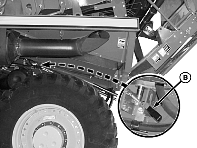
N95991-UN-02DEC11Handler Hydraulic Lock Valve Lever
N87357-UN-17NOV09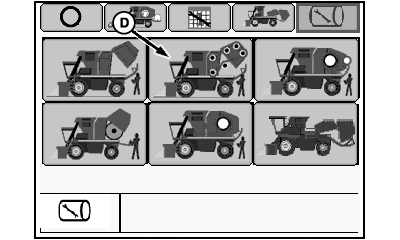
N88295-UN-30MAR10RMB Service Mode Menu
N88032-UN-02MAR10Belt Service Functional Diagram
A - Gate Hydraulic Lock Valve Lever
B - Handler Hydraulic Lock Valve Lever
C - RMB Service Mode Tab
D - Belt Service Mode Icon
Move gate hydraulic lock valve lever (A) and handler hydraulic lock valve lever (B) to locked position. -
Highlight RMB service mode tab (C) and press confirm button to return to RMB service mode menu.
-
Highlight belt service mode icon (D) and press confirm button. Belt service functional diagram screen appears.
-
Press confirm button to view belt service text screen. Press confirm button again to return to functional diagram.
-
CAUTION: Entanglement in moving belts or rollers can cause serious
injury or death. Before operating tether control, make sure that everyone
is clear of moving parts.
Press button A on tether control to run module builder until lace on belt is approximately 450 mm (18 in.) behind rockshaft roller.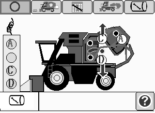
N80428-UN-24APR08 -
Press button C on tether control to raise rockshaft to relieve belt tension.
-
Shut off engine and remove key.
-
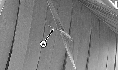
N82414-UN-21JAN09A - Splice Pin
Grip splice pin (A) on belt with pliers and rotate pin 90 degrees (1/4 turn), then pull pin out of lacing. -
Remove staple on replacement belt roll and roll belt out back of machine on ground.
-
IMPORTANT: Replacement belt must be installed with tapered end FIRST and rivets facing DOWN.
Pulley side of factory replacement belts are coated with silicone lubricant to improve belt tracking.
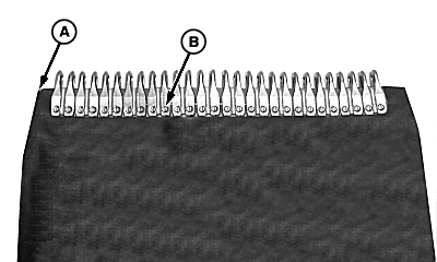
N83564-UN-08APR09A - Tapered End of Belt
B - Rivet Heads
Attach replacement belt to old belt with tapered end (A), against old belt and rivet heads (B) facing DOWN. -
Install splice pin through lacing to connect old belt and replacement belt.
-
Start engine and verify that everyone is clear of module builder.
-
CAUTION: Entanglement in moving belts or rollers can cause serious
injury or death. Before operating tether control, make sure that everyone
is clear of moving parts.
IMPORTANT: Verify that replacement belt tracks in correct location on rockshaft.
Press button A on tether control to run module builder and roll replacement belt into place. Guide old belt out back of machine and have an assistant pull old belt as it comes out of machine.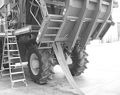
N82412-UN-21JAN09 -
Continue to press button A on tether control until replacement belt is around module builder and old belt is out.
-
Shut off engine and remove key.
-
Remove existing splice pin and connect both ends of replacement belt using replacement pin. Discard old belt and pin.
-
Start engine and verify that everyone is clear of module builder.
-
Press button D on tether control to lower rockshaft and apply tension to belt.
N80428-UN-24APR08 -
Press button A on tether control to run replacement belt and verify proper belt tracking.
-
Disengage hydraulic lock valves.
-
Exit service belts mode and enter RMB service mode.
-
Press button C on tether control to return module builder to closed position.
-
Place tether control unit in storage bracket.
|
DP99999,00007E9-19-20120209 |