Disassembling and Inspecting Slip Clutch
Remove PTO driveline. (See procedure in REMOVING AND INSTALLING PTO DRIVELINE in this section.)
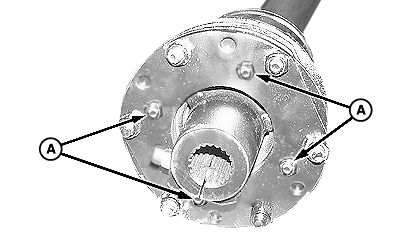
W07845-UN-23MAY06A - Nuts, M8
Remove four M8 nuts (A) from thrust plate studs.NOTE: Belleville spring, which is part of the clutch, keeps tension on all components. When disassembling, release tension by loosening hardware progressively.
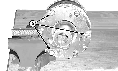
W07969-UN-17JUL06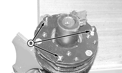
W07970-UN-17JUL06A - Cap Screws and Lock Nuts
B - Cap Screws and Lock Nuts
Place clutch in vise and remove cap screws and lock nuts (A) only.Reposition clutch in vise and loosen cap screws and lock nuts (B) progressively until tension is relieved.
Friction disk may appear to be part of the hub or yoke, tap lightly on edge to separate.
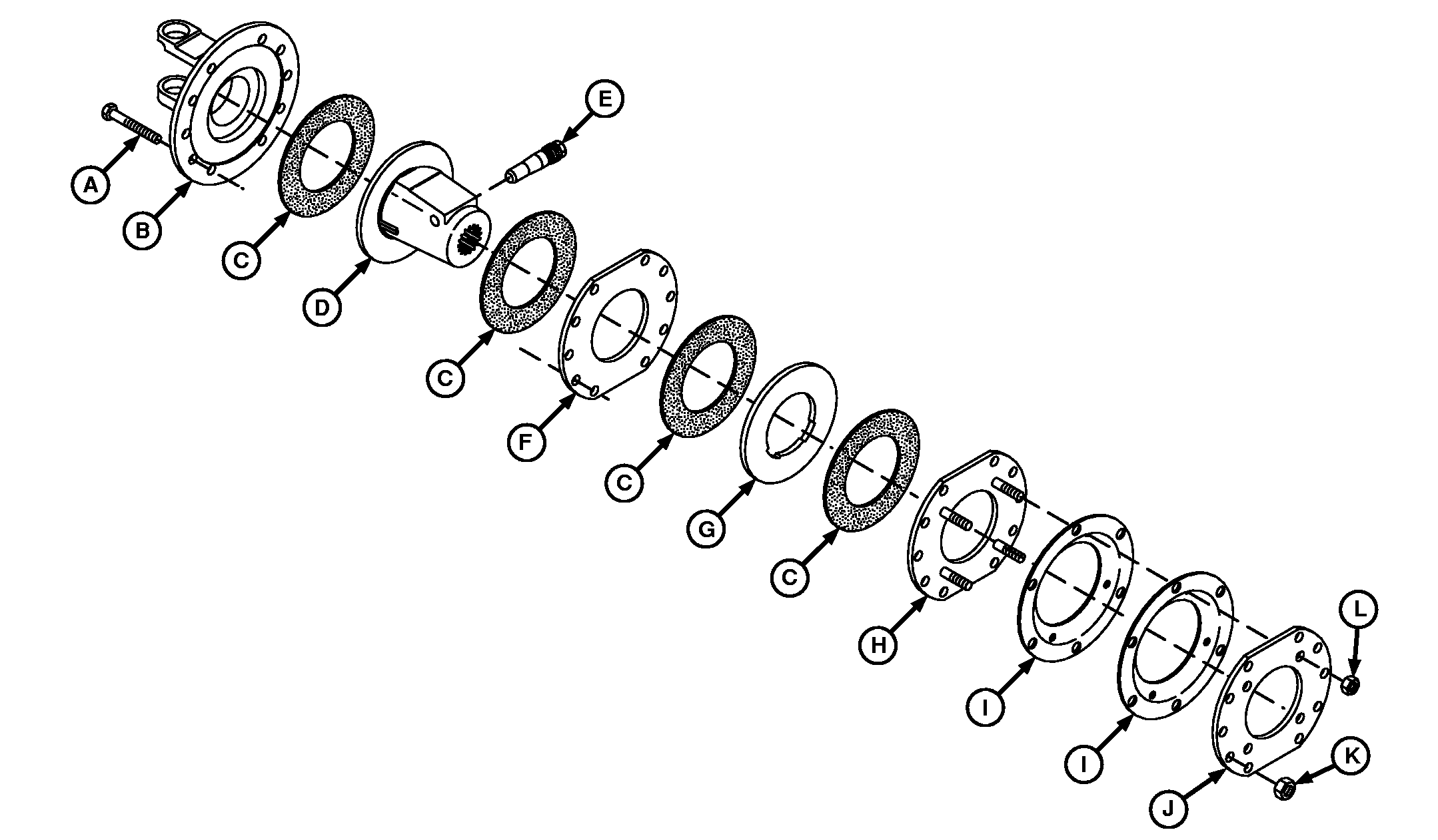
W08429-UN-08JAN07A - Cap Screw, M12 x 85 (6 used)
B - Flange Yoke
C - Friction Disks
D - Hub
E - Screw, Locking
F - Drive Plate
G - Drive Plate
H - Thrust Plate
I - Belleville Springs
J - Backup Plate
K - Lock Nut, M12 (6 used)
L - Nut, M8 (4 used)
Inspect clutch components for wear or damage. Repair or replace parts as necessary.
OUO6038,0001D3F-19-20070108 |