Assembling Slip Clutch
W08431-UN-04JAN07
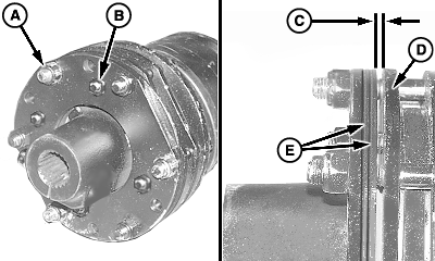
A - Cap Screw and Lock Nut (8 used)
B - Nut, M8 (4 used)
C - Gap
D - Thrust Plate
E - Belleville Springs
Assemble slip clutch in reverse order of disassembly using the following instructions:- Install belleville springs (E) with concave side facing away from yoke end.
IMPORTANT: To avoid driveline damage, DO NOT overtighten cap screws and lock nuts. A gap (C) must be left between thrust plate (D) and belleville springs (E).
Make sure four M8 nuts (B) are loosened before setting gap.
Tighten cap screws and lock nuts (A) leaving a gap (C) between thrust plate (D) and belleville springs (E) according to specifications:Item Measurement Specification Slip Clutch Thrust Plate-to-Spring Gap Distance 4.5 mm (0.177 in.)
OUO6038,0001D40-19-20070109 |