Removing and Installing PTO Driveline
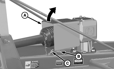
W09185-UN-28NOV07A - PTO Shield
B - Quick-Lock Pin (1 each side)
C - Chain
Disconnect chain (C).Remove quick-lock pins (B) and raise PTO shield (A).
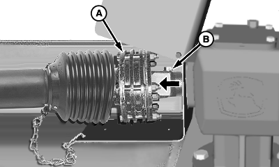
W09192-UN-28NOV07A - Driveline/Clutch Assembly
B - Locking Screw
Remove locking screw (B) from clutch hub.Remove driveline/clutch assembly (A) from gear case input shaft.
Make repairs as necessary:
- Slip clutch service—See DISASSEMBLING AND INSPECTING SLIP CLUTCH in this section.
- Driveline repair—See your John Deere dealer.
Install driveline in reverse order of removal using the following special instructions:
- Apply multipurpose grease on gear case input shaft.
- Align hole in hub with groove in input shaft and install locking screw. Tighten screw to specification.
Item Measurement Specification Locking Screw Torque 150 N˙m (110 lb-ft)
OUO6038,0001D5A-19-20071128 |