Adjusting Cutting Height and Angle
 CAUTION: Help prevent bodily injury or death caused by entanglement in rotating driveline or blades. Disengage PTO, engage parking brake and/or place transmission in PARK, shut off tractor engine, and remove key before making adjustments.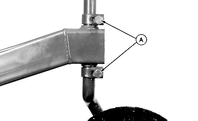
W02425-UN-24MAY96A - Clamps
Raise tailwheel to highest position:Loosen clamps (A).
Lift wheel support.
Retighten clamps.
Using tractor rockshaft control lever, position front of cutter at desired cutting height.
Adjust tractor rockshaft depth stop. (See your tractor Operator’s Manual.)
NOTE: Maintain this angle at all cutting height positions to reduce power requirements and produce the best cutting results.
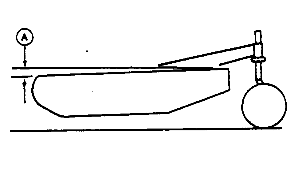
W9290-UN-12MAY89A - Dimension, 25 mm (1 in.)
Adjust center link so rear of cutter is higher than front. Dimension (A) should be within specification.Item Measurement Specification Cutter Rear-to-Front Distance 25 mm (1 in.)
W02425-UN-24MAY96A - Clamps
Loosen clamps (A), lower tailwheel to ground, and tighten clamps.IMPORTANT: Loosening the center link may allow the driveline to contact the cutter frame. Raise the cutter slowly and check for interference. Lengthen tractor lift links to provide clearance to full lift height.
NOTE:
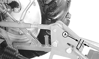
W08378-UN-10NOV06A - Dimension, 12.5 mm (1/2 in.)
The tailwheel supports the rear and the draft links support the front to allow the cutter to follow the ground.Adjust center link so dimension (A) is within specification.
Item Measurement Specification Hitch Plate-to-Brace Clearance 12.5 mm (1/2 in.)
OUO6077,00019EC-19-20061110 |