Assemble Rotary Cutter
W08349-UN-07NOV06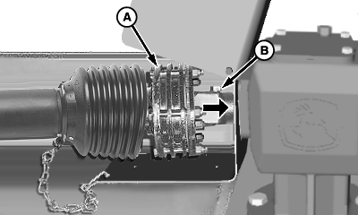
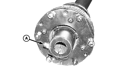
W09197-UN-30NOV07A - Locking Screw
B - Slip Clutch Hub
Loosen screw (A) on slip clutch hub.Remove paint from gear case input shaft splines using wire brush.
Apply multipurpose grease on gear case input shaft.
Attach slip clutch (B) end of driveline to gear case input shaft.
Align hole in hub with groove in input shaft and install cap screw and lock nut. Tighten screw to specification.
Item Measurement Specification Screw Torque 150 N·m (110 lb-ft) 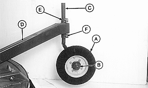
W02453-UN-26MAR96A - Tire
B - Hub
C - Pivot
D - Support
E - Clamp
F - Cap Screw, M16 x 70 (2 used)
Attach wheel and tire (A) to hub (B) using four 1/2 x 1-1/2 in. bolts, lock washers and nuts. Tighten to specification.Item Measurement Specification Nuts Torque 110 N·m (80 lb-ft) Install pivot (C) in wheel support (D) and attach using two clamps (E), M16 x 70 cap screws (F) and lock nuts.
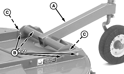
W08351-UN-07NOV06A - Tailwheel
B - Cap Screws
C - Shims (as needed)
Attach tailwheel (A) to cutter using four 5/8 x 3-1/4 in. cap screws (B) and lock nuts. Add shims at (C) as necessary.Tighten to specification.
Item Measurement Specification Lock Nuts Torque 215 N·m (160 lb-ft) 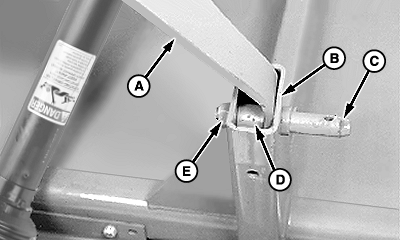
W08352-UN-08NOV06A - Hitch
B - Support
C - Hitch Pin
D - Bushing
E - Lock Nut, 7/8 in.
Remove two hitch pins and bushings.Insert hitch pin (C) through support (B), hitch (A), and bushing (D).
Fasten using 7/8 in. lock nut (E). Tighten to specification.
Item Measurement Specification Lock Nut Torque 590 N·m (435 lb-ft) Repeat on opposite side.
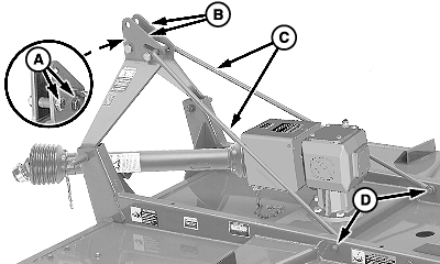
W09198-UN-03DEC07A - Cap Screws, 1 x 4 in., Bushings and Lock Nuts
B - Hitch Plates
C - Brace
D - Cap Screws and Lock Nuts, 5/8 x 3-1/4 in.
Remove brace (C) from shipping position.Route brace (C) through both hitch plates (B) and attach to cutter frame using two 5/8 x 3-1/4 in. cap screws and lock nuts (D). Tighten lock nuts to specification.
Item Measurement Specification Lock Nuts Torque 215 N·m (160 lb-ft) Connect hitch plates using two 1 x 4 in. cap screws, bushings (between plates), and lock nuts (A).
Attach driveline safety chain to gear case shield.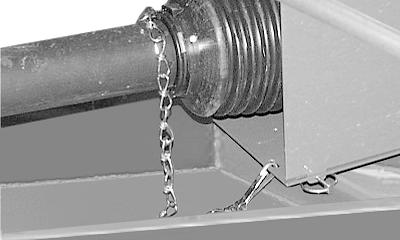
W08355-UN-16JAN07NOTE: Driveline is shipped with screw (A) installed to prevent driveline from extending.
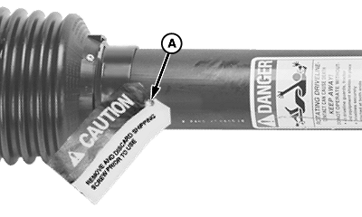
W08356-UN-09NOV06A - Screw
Remove and discard screw (A) and tag.
OUO6077,0001A05-19-20071205 |