Guidance Setup
![]()
PC8663-UN-05AUG05
MENU button

PC12685-UN-14JUL10
GREENSTAR 3 Softkey

PC12947-UN-12OCT10
GUIDANCE Softkey
PC11792-UN-09MAR09
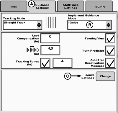
Guidance Settings
A - Guidance Settings Tab
B - Implement Guidance Mode
C - iGuide Settings
Guidance Setup
MENU >> GREENSTAR >> GUIDANCE softkey >> GUIDANCE SETTINGS tab (A)
Select desired Tracking Mode first (refer to AutoTrac Operators Manual). If Curve Track was selected, check Curve Track settings.
Set Implement Guidance Mode (B) to iGuide.
Select iGuide Settings (C) to define Slope Compensation and iGuide sensitivity.
For information on Turning View, Turn Predictor, Lead Compensation, Arrow Segments, and Tracking Tones refer to the AutoTrac Operators Manual.
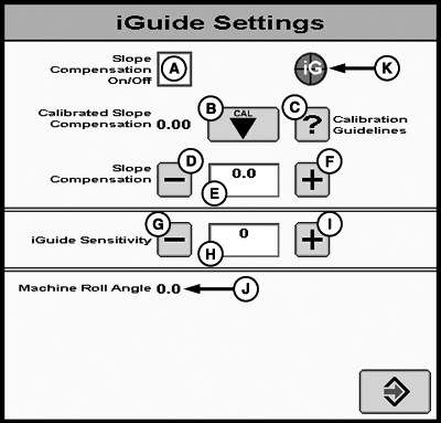
PC11793-UN-10MAR09
A - Slope Compensation On/Off
B - Calibrated Slope Compensation Button
C - Slope Calibration Help Button
D - Decrease Slope Compensation Value
E - Calibrated Slope Compensation Value
F - Increase Slope Compensation Value
G - Decrease iGuide Sensitivity
H - iGuide Sensitivity Input
I - Increase iGuide Sensitivity
J - Machine Roll Angle
K - iGuide Status Pie
Slope compensation aids in helping drive the machine up a hill to account for implement drift. It looks at the machine roll angle and slope compensation value to determine the amount to move the machine up hill. On a 5 degree slope with a value of 2.54 cm (1.0 in.)/degree this will move the machine 12.7 cm (5 in.) up the hill to compensate for the implement drifting down hill. If the implement drifts more than that, increase the slope compensation value. If the implement drifts less than that, decrease the slope compensation value.
- Unless the field is completely flat, the slope compensation value can aid in keeping the implement on line.
- 0-2 degrees—Slope compensation may not be needed. Recommended starting value 1.3 cm (0.5 in.)/degree.
- 2-5 degrees—Slope compensation provides a moderate amount of machine correction and is recommended to be turned on. Typical values of 1.3 to 3.8 cm (0.5 to 1.5 in.)/degree.
- 5 degrees and above—Slope compensation is recommended to be on. Typical values can range from 2 to 7.6 cm (0.8 to 3.0 in.)/degree.
Recommendation for use:
NOTE: Values above 7.6 cm (3 in.)/degree should be used with caution. On a 10 degree slope with a value of 7.6 cm (3 in.)/degree, the system will try to move the machine 76 cm (30 in.) up hill to compensate for implement drift.
- Machine and Implement should be tracking on line with iGuide activated. Do not perform the calibration during line acquisition.
- If the current slope compensation value is more than 1.3 cm (0.5 in.)/degree difference, it may be better to enter the value manually with the increment and decrement buttons. If a large change is made, it could cause some system instability until the system has time to react to the large changes.
- Calibrations made at roll angles between 2-5 degrees may not be ideal for larger roll angles and vice versa.
Using the Calibration Feature:
NOTE: You cannot navigate away from the iGuide screen while calibrating slope compensation. Stop calibration then navigate to other screens.
- When transiting to a hillside and implement error is showing the implement needs to move down hill, slope compensation needs to be reduced.
- If the implement error is showing implement needs to move up hill, slope compensation value should be increased.
Adjusting the value manually:
When slope compensation (A) is checked, slope compensation will be turned on.
Calibrated slope compensation displays the last slope compensation value created during calibration.
Slope compensation (E) is an input field allowing for manual adjustment of the slope compensation value and shows current compensation value.
Adjusting Slope Compensation Value
Slope Compensation can be changed by three methods:
- Calibrate slope compensation by pressing (B). Also see GUIDANCE SETUP for detailed information.
- Use decrement (D) and increment (F) buttons to change slope compensation value (E).
- Manually enter Slope Compensation value (E).
Adjustment for slope compensation using decrement (D) and increment (F) buttons is 0.01 cm (0.01 in.)/degree.
NOTE: Average slope compensation range is 1.3 to 8.9 cm/degree (0.5 to 3.5 in./degree). If value is higher, re-calibrate. If value is still too large, turn off slope calibration. This can typically be seen on flat ground.
NOTE: If upon calibration, slope compensation value is above 4.00, calibrate again. Re-calibration is recommended to verify a consistent slope compensation value. If a consistent value is not achieved, review the slope compensation guidelines in the GUIDANCE SETUP section.
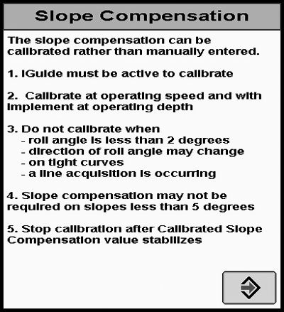
PC11794-UN-09MAR09
Slope Compensation
- iGuide must be active to calibrate
- Calibrate at operating speed and with implement at operating depth
- Do not calibrate when
- Roll angle is less than 2 degrees
- Direction of roll angle may change
- On tight curves
- A line acquisition is occurring
- Slope compensation may not be required on slopes less than 5 degrees
- Stop calibration after calibrated slope compensation value stabilizes
The slope compensation can be calibrated rather than manually entered.
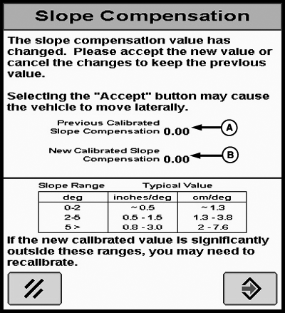
PC11795-UN-09MAR09
Slope Compensation
A - Previous Calibrated Slope Compensation
B - New Calibrated Slope Compensation
The slope compensation value has changed. Please accept the new value or cancel the changes to keep the previous value.
Selecting the “Accept” button may cause the vehicle to move laterally.
Typical Values for Slope Compensation Calibration
Slope Range | Typical Value | |
|---|---|---|
Degree | Inches / Degree | Centimeter / Degree |
0 - 2 | ~ 0.5 | ~ 1.3 |
2 - 5 | 0.5 - 1.5 | 1.3 - 3.8 |
5 > | 0.8 - 3.0 | 2 - 7.6 |
If the new calibrated value is significantly outside these ranges, you may need to recalibrate.
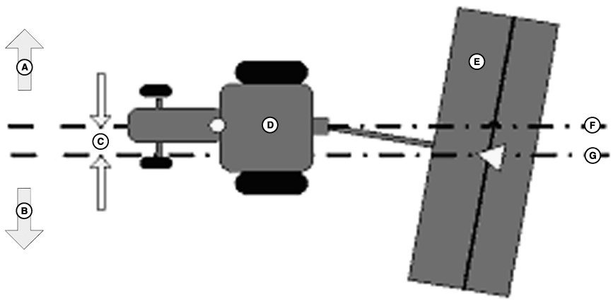
PC11062-UN-29FEB08
10 Degree Slope Compensation
A - Up Hill
B - Down Hill
C - 25.4 cm (10 in.)
D - Tractor
E - Implement
F - Desire Path
G - Implement Drift Path
Calculating Slope Compensation Manually
If the center of the machine and center of the implement positions are 25.4 cm (10 in.) apart on a slope with a roll angle of 10 degrees, the slope compensation value should be set to 2.54 cm (1 in.) per degree (25.4 cm (10 in.) of drift divided by 10 degrees of roll angle). If there is a 25.4 cm (10 in.) difference on a slope with a 5 degree roll angle, then the value would be 5.1 cm (2 in.)/degree.
Implement Error / Roll Angle = Slope Compensation
NOTE: Recommended adjustment in 0.2 cm (0.05 in.)/deg.
- iGuide Sensitivity allows the system to respond to implement errors. Higher sensitivity enables iGuide to quickly react to implement error.
- Too high of a value may cause the system to oscillate around the intended path. Too low of a value may cause the implement to react slow when trying to maintain the implement on the guidance path.
- A starting value of 15 is recommended. Adjust the sensitivity in small increments until optimal tracking performance is achieved.
iGuide Sensitivity
iGuide Sensitivity affects how aggressively the system responds to implement error. This function is similar to AutoTrac steer sensitivity.
NOTE: Machine steer sensitivity may need to be increased or decreased to keep the machine on the guidance path. iGuide is dependent on the machines ability to track accurately on the intended guidance path.
CZ76372,00001DD-19-20101012 |