Initial Settings
NOTE: Please refer to the COMPATIBILITY section for components compatible with the GreenStar Rate Controller.
-

PC12542-UN-08APR10
PC12543-UN-08APR10A - Section Valve Type Drop-Down Menu
B - Constant Flow Enable/Disable Box
C - 3-Wire
D - 2-Wire
Select Section Valve type (A) from the drop-down menu. See MAXIMUM NUMBER OF IMPLEMENT SECTIONS table and valve type descriptions. -
Select the Constant Flow enable/disable box to configure the GreenStar Rate Controller to operate with section valves that have a continuous flow bypass. Steps for calibrating section bypass valves are described in the SECTION TEST section of this manual.
-
 CAUTION: Selecting the wrong valve type can result in valves
opening unexpectedly. To avoid injury from exposure to chemicals,
verify the correct valve is selected. Review control valve type before
moving GreenStar Rate Controller between implements.
CAUTION: Selecting the wrong valve type can result in valves
opening unexpectedly. To avoid injury from exposure to chemicals,
verify the correct valve is selected. Review control valve type before
moving GreenStar Rate Controller between implements.IMPORTANT: For PWM and PWM Close Control Valve systems, it is recommended that an external solution pump on/off switch is wired into the cab if not already present, allowing the operator to shut off the solution pump. Solution pump damage may occur if pump is run without solution in it.
PWM Control Valve System: When the master switch is shut off on a PWM Control Valve System, it will close the section on/off valve stopping product flow. The PWM Valve will remain at its current position allowing hydraulic flow to continue to the solution pump which will allow the solution pump to continue running. An external solution pump on/off switch will allow the operator to shut off the solution pump.
PWM Close Control Valve System: When the master switch is shut off on a PWM Close Control Valve System, it will shut off the solution pump. An external solution pump on/off switch can be more user-friendly and familiar for a sprayer operator to shut off the solution pump if the solution tank runs empty.
Refer to the solution pump manufacturer’s Operators Manual for more information.

PC12236-UN-10SEP09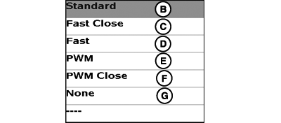
PC12544-UN-08APR10A - Control Valve Type Drop-Down Menu
B - Standard
C - Fast Close
D - Fast
E - PWM
F - PWM Close
G - None
Select Control Valve type from the drop-down menu.Select Control Valve Type "None" for systems that do not have a Control Valve. An example would be Dragline manure applications that do not have a Control Valve.
NOTE: Valve type must be selected for the system to work. Select Standard, Fast, or PWM for valve configurations with a control valve and separate downstream on/off valve(s). Select Fast Close or PWM Close for valve configurations with one valve that combines control and on/off. Selecting the wrong valve type may result in unexpected behavior and degraded performance.
-
PC12237-UN-10SEP09
PC12238-UN-10SEP09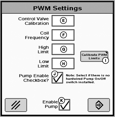
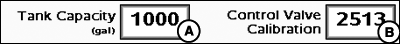
PC14149-UN-01NOV11A - Tank Capacity Input Box
B - Control Valve Calibration
C - Tank Capacity Input Box
D - PWM Setup Button
E - Control Valve Calibration Input Box
F - Coil Frequency Input Box
G - High Speed Limit Input Box
H - Low Speed Limit Input Box
I - Calibrate Limits Button
J - Pump Enable Checkbox
K - Enable Pump
Enter maximum volume of tank in input box labeled tank capacity. Tank capacity range is 0 to 17,000 and it will default to 1000 gal or 3785 liters. -
Standard, Fast, and Fast Close Control Valves
Enter the Control Valve Calibration number in the input box (B). Continue to Step 9.
PWM and PWM Close Control Valves
Press the PWM Setup Button (D) and enter the Control Valve Calibration number in the input box (E). Continue to Step 6.
NOTE: For PWM and PWM Close control valves, the Raven calibration number of 0043 is NOT optimal for GreenStar Rate Controller System. If the PWM or PWM Close control valve is not referenced in the chart below start with 1533 and use the process below to fine tune the calibration value for optimal performance.
Fine tuning the Control Valve Calibration Number for Optimal Performance.
Use recommended values in Control Valve Calibration table to initially set control valve number. Evaluate machine behavior during operation, and if necessary, adjust value to attain optimum system performance.
The Control Valve Calibration number is a 4 digit number used to fine tune control characteristics. The number is in the form XXYZ, and is defined as follows:
-
XX - Valve Speed.
-
The higher this value, the quicker the valve responds. If it
is set too high, actual flow rate will oscillate continuously around
target rate. If it is set too low, target rate will never be reached.
-
The higher this value, the quicker the valve responds. If it
is set too high, actual flow rate will oscillate continuously around
target rate. If it is set too low, target rate will never be reached.
-
Y - Output Deadband.
-
Sets the minimum speed that the valve will ramp down toward
before stopping. The higher this value, the sooner the valve will
become stationary.
-
Sets the minimum speed that the valve will ramp down toward
before stopping. The higher this value, the sooner the valve will
become stationary.
-
Z - Control Deadband:
- Sets how close actual flow rate must be to target rate to be considered acceptable. When actual and target rates are within this range, the valve will remain stationary. A higher value allows for a larger disparity between actual and target rate.
NOTE: Look for low variance in the lpm (gpm) operating range that the system applies in the field when completing the Configuration Test.
Example of tuning the control valve for optimal response:After entering the initial starting value for the control valve (e.g. 2513) and run a configuration test, the variance runs high (at or near 100%) and the valve response seems sluggish. The next step in tuning may be to increase the valve speed number (first 2 digits) from 25 to 35 and also increase the output deadband number (third digit) from 1 to 2 and retry the configuration test. Running a nozzle flow check is also a good way to obtain a better feel for valve speed and response time of the system.
Standard Valve Type
Valve Calibration Number (XXYZ)
RAVEN 165
2513
RAVEN 894
2513
RAVEN 125
2513
TEEJET 344B
1003
HARDI
7051
Fast Valve Type
Valve Calibration Number (XXYZ)
RAVEN 177
0753
HINIKER Servo Valve (8160 Monitor Compatible)
0433
KZCO Servo Valve (JD 2510 Liquid Fertilizer system)
1031
Fast-Close Valve Type
Valve Calibration Number (XXYZ)
RAVEN 177
0753
HINIKER Servo Valve (8160 Monitor Compatible)
0433
KZCO Servo Valve (JD 2510 Liquid Fertilizer system)
1031
PWM Valve Type
Valve Calibration Number (XXYZ)
Sauer Danfoss Hagie MFG T540
1533
Command Controls Corporation FV1501
1411
PWM-Close Valve Type
Valve Calibration Number (XXYZ)
Sauer Danfoss Hagie MFG T540
1533
Command Controls Corporation FV1501
1411
NOTE: On a RAVEN valve, the last three numbers of the model number are used to identify the valve type (Example: RAVEN XXX894).
-
XX - Valve Speed.
-
Enter the Coil Frequency for the PWM/PWM Close valve in input box (F). Refer to control valve manufacturer's Operator's Manual to attain the proper Coil Frequency value. The Coil Frequency will default to 122.
-
Define PWM Limits to control the minimum/maximum desired flow or pressure to prevent machine damage and ensure quick system response. Defining limits can be done by manually entering the high and low limits into the input boxes (G & H) or by using the Calibrate PWM Limits Test (I). The high and low limits range is 0-255. See Calibrate PWM Limits Test in the Tests Section for details on how to perform the test.
-
Check Pump Enable Checkbox (J) if there is no hardwired pump On/Off switched installed. Enable Pump (K) will override the PWM signal to shut off the pump anytime it is unchecked.
NOTE: Check Pump Enable Checkbox if there is no hardwired Pump On/Off switch installed.
-
PC12545-UN-08APR10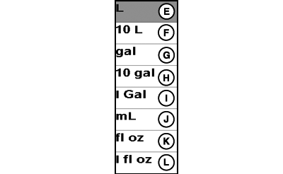
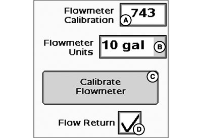
PC12546-UN-08APR10Flowmeter Units Drop-Down Menu
A - Flowmeter Calibration Input Box
B - Flowmeter Units Drop-Down Menu
C - Calibrate Flowmeter Button
D - Flow Return Enable / Disable Box
E - L (Liter)
F - 10 L (10 Liter)
G - gal (gallon)
H - 10 gal (10 gallon)
I - I Gal (Imperial Gallon)
J - mL (milliliter)
K - fl oz
L - I fl oz (Imperial fluid once)
Enter Flowmeter Calibration number as stamped on valve.Most flowmeters have an attached tag indicating the recommended calibration number. Enter this number as the initial Flowmeter Calibration value. The Calibrate Flowmeter test must be run to attain a more accurate flowmeter calibration number (see Calibrate Flowmeter test).
NOTE: If the tag is no longer attached, start with a low calibration number such as 60. Conduct a Calibrate Flowmeter test, and the system will adjust the value accordingly.
-
Choose unit of measurement from flowmeter units drop-down.
NOTE: The number on the RAVEN tag is pulses per 10 units of fluid. Ensure the 10 gal / 10 L unit is used when using the number straight off the RAVEN tag.
NOTE: For manure applications using a Krohne Flowmeter, ensure the pulses/gallon are set to 2 or higher. Please see the Krohne Operators Manual for further detail.
-
To calibrate Flowmeter, select button and follow on screen instructions. See Test section for details.
-
Flow Return— A Flow Return option is available for liquid systems equipped with a positive displacement pump. With this feature selected, the GreenStar Rate Controller will open a flow return valve whenever all section valves are closed in order to reduce system pressure. The flow return valve will remain closed if one or more section valves are open. Refer to the TROUBLESHOOTING section to determine which driver numbers and connector pins are associated with the flow return valve.
-
Check the pressure sensor box if sensor is installed. If using more than one pressure sensor, check the second box as well. Pressure indicator will be displayed on main menu instead of flow rate when pressure sensor is checked.
-
To calibrate pressure sensor(s), select button and follow on screen instructions. See Test section for details.
-
PC12975-UN-27OCT10Initial System Settings
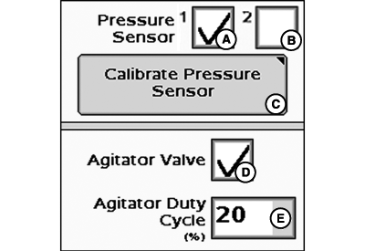
A - Pressure Sensor 1 Enable/Disable Box
B - Pressure Sensor 2 Enable/Disable Box
C - Calibrate Pressure Sensor Button
D - Agitator Valve Enable/Disable Box
E - Agitator Duty Cycle Drop-Down Menu
Check the agitator valve box to enable agitator.NOTE: Agitator valve selection may reduce the number of implement sections the GS2 can control. See maximum number of implement sections table.
-
Set agitator duty cycle percent from drop-down menu. Agitation Rate is based on runtime in ten minute intervals. Example: at 20% agitator runs for 2 minutes and is off for 8 minutes.
If the tank volume is at or below 20% of the total volume of the tank the agitation will reduce to half the set run time. Example: at the 20% setting from the example above, the agitation will now run for 1 minute and is off for 9 minutes.
|
BA31779,00002A9-19-20111103 |