Create Boundaries
NOTE: Exterior and interior boundaries must be driven. Exterior headland and interior headland boundaries can either be driven or created automatically using top and bottom headlands or constant offset headlands.
NOTE: A boundary cannot intersect itself. Press Record/Pause button to pause recording just prior to stopping. Always start moving forward first before pressing Record/Pause button to begin recording again.
Creating Driven Boundaries and Headlands
-
Select Mapping > Boundaries tab.
-
Select Client, Farm, and Field from drop-down.
-
Select Boundary Type from drop-down.
-
For exterior headlands, select Driven from Creation Method drop-down. For interior headlands, select Drive Boundary check box.
-
Enter distance from GPS receiver to edge of field.
-

PC17820-UN-03OCT13A - Record and Pause Boundary Recording
B - Toggle
C - Stop Recording
D - Recording Indicator Light
Select Toggle (B) to set boundary left or right of machine receiver, or left or right of position of implement.NOTE: If set from implement, location is left or right of rear of implement.
When toggling button to change recording position, set recording as paused or off.
-
Select Record and Pause (A) 1 sec. or more after machine starts moving forward. Recording Indicator Light (D) blinks red and pink when recording is on. Select button again to Pause and drive around an obstacle. Recording Indicator Light is solid red when paused. When Record and Pause is selected again, recording resumes. Boundary displays a straight line from where recording was paused to where it was resumed.
NOTE: If using iTEC™ Pro, leave recording on when navigating an obstacle so iTEC™ Pro alerts operator of obstacle.
-
If recording was started along a straight section of boundary, select Stop (C) after turning last corner near straight section. If recording was started in a corner, select Stop before point where recording was started. Make sure point where recording is stopped does not intersect point where it was started. Selecting Stop completes boundary by showing a straight line between point where it was stopped and starting point.
PC17397CC-19-21AUG14
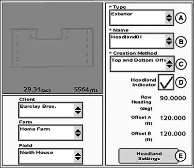
Creating Top and Bottom Headlands
NOTE: An Exterior boundary must exist in field.
This option is not available for interior headlands.
-
Select Exterior Headland from Type drop-down menu.
-
Enter name of headland boundary in Headland Group drop-down menu. Several headland boundaries can be saved in a field for different implement widths. For example, if planter is a 16R30 and two passes are planted in headland, enter 24.4 m (80 ft.).
-
Select Headland Settings button to make adjustments to Row Heading (A), Offset X (B), and Offset Y (C). These are default settings for approximate heading of rows in field, and width of headlands on ‘X’ and ‘Y’ ends of field.
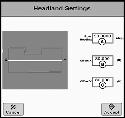
PC10504CC-19-24OCT13A - Row Heading
B - Offset X
C - Offset Y
Heading entered does not need to be the exact heading. For example, if heading for AutoTrac™ AB line is 85 degrees, entering 90 degrees creates headlands on east and west ends of field. During tillage work, if work is being done at 30 degrees from east and west, entering 120 degrees gives headlands on all sides of field. In this case, Constant Offset headlands could also be used.
Efforts have been made to make the most logical headlands based on way fields are normally farmed. If desired headlands are not coming out as expected, change Row Heading to several angles close to direction of travel. If still not satisfactory, a Driven Headland boundary needs to be recorded.
NOTE: Top and bottom headlands are calculated as offsets and may not be appropriate for all fields. Headlands are created when Row Heading is more than 15 degrees from any side of field.
Defaults for Offsets X and Y are twice the implement width, as entered from Machine and Implement page. Width of each headland can be changed. For example, if west end has 32 76.2 cm (30 in.) headland rows, and East end has 48 76.2 cm (30 in.) headland rows, enter 24.4 m (80 ft.) for X and 36.6 m (120 ft.) for Y.
Creating Constant Offset Headlands
NOTE: An Exterior or Interior boundary must exist in field.
-
Select Exterior Headland or Interior Headland from Type drop-down menu.
-
Enter name of headland boundary in Headland Group drop-down menu. Several headland boundaries can be saved in a field for different implement widths.
-
In Boundary Offset input box, enter distance from headland to boundary (For example, if planter is a 16R30 and two passes are planted in headland, enter 24.4 m (80 ft.).
|
iTEC is a trademark of Deere & Company AutoTrac is a trademark of Deere & Company |
CZ76372,0000723-19-20140821 |