Detach Bucket or Attachment—520M Loaders
Global Carrier
-
 CAUTION:
X9811-UN-23AUG88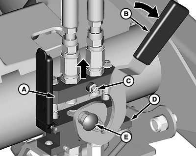
W24164-UN-26AUG13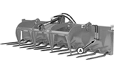
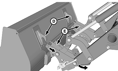
W24304-UN-18OCT13Hay Grapple Attachment Shown
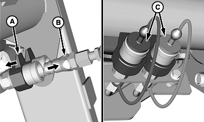
W24165-UN-18OCT13A - Coupler, Attachment
B - Lever
C - Pin (1 each side)
D - Coupler, Loader
E - Red Knob
F - Cover
Escaping fluid under pressure can penetrate the skin causing serious injury. Avoid the hazard by relieving pressure before disconnecting hydraulic or other lines. Protect hands and body from high-pressure fluids. See additional information, Avoid High-Pressure Fluids in Safety section.Prevent bodily injury. DO NOT allow bystanders near the loader while detaching the bucket or attachment. Allow only the tractor operator to detach the bucket or attachment.
NOTE: Procedure is the same for all attachments. Bucket attachment shown.
Close grapple or attachment. Level the bucket and lower to the ground.
-
Relieve hydraulic pressure. (See Relieve Hydraulic Pressure in Controls section.)
-
If equipped with hydraulic-operated attachment, such as a grapple, disconnect the hydraulics as follows:
Multicoupler configuration:
-
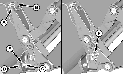
Push in red knob (E) and rotate lever (B) upward to disengage pins (C) and separate the coupler halves.
-
Remove attachment coupler (A) from loader coupler (D). Place coupler with hoses on attachment as shown.
-
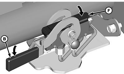
IMPORTANT: Prevent possible interference with tractor components. Lever (B) must be in the locked (DOWN) position when the attachment coupler half is removed. Lower cover (F) to protect the connection surface of the loader coupler.
Close cover (F) and rotate lever (B) downward to lock in place.
-
-
W24166-UN-26AUG13A - Coupler, Female
B - Coupler, Male
C - Plugs
Quick coupler configuration:-
Push and hold collar (A) on the female coupler
-
Disconnect male coupler (B).
-
Release collar on the female coupler
-
Place cap on the male tip at the hose end and insert plug (C) into the female coupler.
-
Repeat steps for the remaining hose connection.
-
-
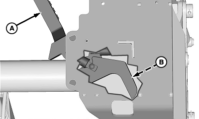
W24167-UN-26AUG13A - Carrier
Retract bucket cylinders until the bucket is resting on carrier (A) as shown. -
W24168-UN-26AUG13Latch Lever
W24169-UN-22AUG13Latch Pins Retracted (Underside)
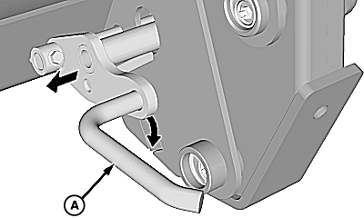
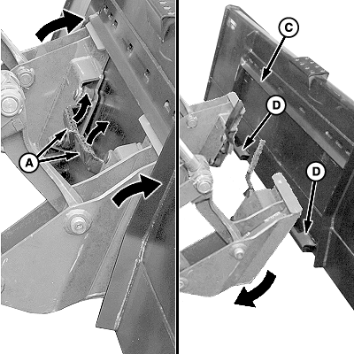
W24170-UN-28AUG13A - Lever
B - Pin, Left-Hand Side
C - Pin, Right-Hand Side
D - Hooks
E - Carrier Arms
Place transmission in PARK and shut off engine. -
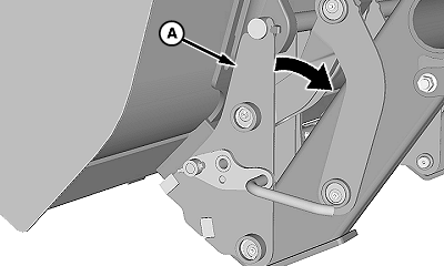
Pull latch lever (A) outward and clockwise to disengage latch pins (B and C) from the bucket.
NOTE: Latch handle (A) remains open and ready for latching.
-
Place transmission in NEUTRAL allowing for tractor movement.
-
Extend bucket cylinders and lower the loader to the ground allowing carrier arms (E) to clear hooks (D) on the bucket.
-
CAUTION: Prevent bodily injury from a pinching hazard. If not
immediately attaching to another attachment, fully roll back the carrier
to engage the latch pins.
Place transmission in REVERSE and back away from the bucket.
500-Style Carrier
-
CAUTION: Prevent bodily injury. DO NOT allow bystanders near
the loader while detaching the bucket or attachment. Allow only the
tractor operator to detach the bucket or attachment.
NOTE: Procedure is the same for all attachments. Bucket attachment shown.
W24171-UN-28AUG13Left-Hand Side Shown
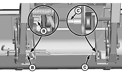
A - Carrier
B - Hook (1 each side)
C - Pin, Bucket (1 each side)
D - Strap (1 each side)
E - Pin, Quick Lock (1 each side)
F - Storage Position (1 each side)
Retract bucket cylinders and raise the loader approximately 460 mm (18 in) from the ground. -
Place transmission in PARK and shut off engine.
-
Remove quick lock pin (E) from each side of the bucket.
-
Store pins in storage position (F).
-
Extend bucket cylinders until the pin (C) releases from carrier strap (D) on each side of the bucket.
-
Lower loader, place transmission in REVERSE and move away from the bucket. Carrier (A) releases from hooks (B) on each side of the bucket.
Skid-Steer Carrier
-
CAUTION: Prevent bodily injury. DO NOT allow bystanders near
the loader while detaching the bucket or attachment. Allow only the
tractor operator to detach the bucket or attachment.
NOTE: Procedure is the same for all attachments. Bucket attachment shown.
W08389-UN-29NOV06Left-Hand Lock Pin
W08399-UN-28NOV06A - Latch Handles
B - Lock Pin (1 each side)
C - Lip
D - Latches
Position machine on flat, level surface. Level bucket and lower the loader to the ground. -
Place transmission in PARK and shut off engine.
-
IMPORTANT: Prevent possible machine damage. Make sure that both latch handles (A) are up and lock pins (B) are fully retracted.
Raise both latch handles (A) to the UP (unlatched) position.
-
Place transmission in NEUTRAL. Extend bucket cylinders until the carrier clears the bottom latches (D).
-
Place transmission in REVERSE and back away from the bucket.
|
OUO6064,0001CED-19-20170718 |