Installing and Using Clevis Assembly Cat 3 Drawbar
RXA0084675-UN-20OCT05
RXA0085836-UN-10JAN06
RW26281-UN-12JUN99
RW26282-UN-12JUN99
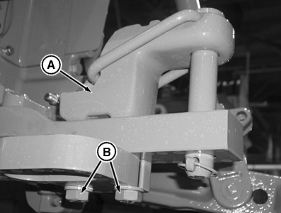
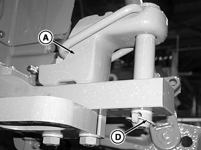
A - Clevis Assembly
B - Cap Screw
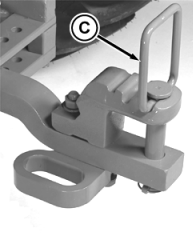
C - Pin with Handle
D - Locking Pin
IMPORTANT: The clevis may need to be removed depending on application.
Clevis assembly (A) must be attached ONLY to top of drawbar.
Install clevis assembly and tighten cap screws (B).
| Item | Measurement | Specification |
| Clevis Assembly Retaining Cap Screws | ||
| Category 3 | Torque | 750 N·m (550 lb-ft) |
Remove locking pin (D). Lift pin with handle (C) and position in notch of clevis assembly.
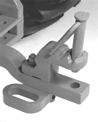
Attach implement.
Insert pin only through drawbar, not through clevis assembly, if towed implement also has a clevis assembly. DO NOT insert pin through all four members.
Install locking pin (D).
ZE59858,0000475-19-20101130 |