Changing Reversible PTO Stub Shaft—Type 1, Type 2 PTO (If Equipped)
RW21879A-UN-02AUG99
RW21883A-UN-02AUG99
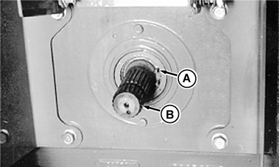
A - Snap Ring
B - Shaft
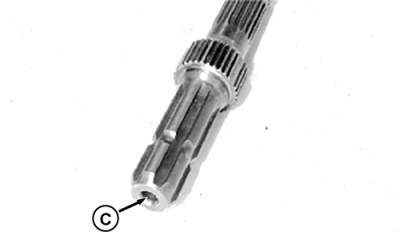
C - Bore
 CAUTION: Avoid personal injury. PTO shaft may be hot from operation. Allow shaft to cool before changing.
IMPORTANT: Implements can be operated with 540 rpm 35 mm (1-3/8 in.) stub shaft only if the power input never exceeds 60 kW (80 hp). Operating PTO at lower speeds under heavy load could damage PTO. The 1000 rpm 35 mm (1-3/8 in.) stub shaft should be used for loads under 115 kW (154 hp).
Rotate ends of snap ring to align with flat surface of PTO stub shaft.
Remove snap ring (A) and pull out shaft (B).
Clean stub shaft thoroughly. Coat splines with John Deere HD Non-Clay grease.
IMPORTANT: Avoid damage to PTO. Clean bore (C) thoroughly when installing PTO shaft for 1000 rpm use.
Install shaft into PTO housing.
540 rpm shaft—Rotate shaft back and forth while installing, to ensure that shaft is properly seated in housing; continue to push shaft in while installing snap ring.
1000 rpm shaft—Rotate shaft back and forth while installing until engagement is felt.
NOTE: Shaft is properly engaged when shaft turns with high effort.
Install snap ring in groove to retain PTO stub shaft. Align ends of snap ring with flat surface of shaft.
IMPORTANT: Make sure to select either 540 or 1000 rpm mode after changing PTO shaft.
Select correct PTO shaft mode. (See Rear PTO Mode Lever Position (If Equipped) in this section.)
ZE59858,000047C-19-20101130 |