Installing Video Display Camera (Touchscreen CommandCenter™ Only, Equipped with 2630 Display)
RXA0107925-UN-28MAY10
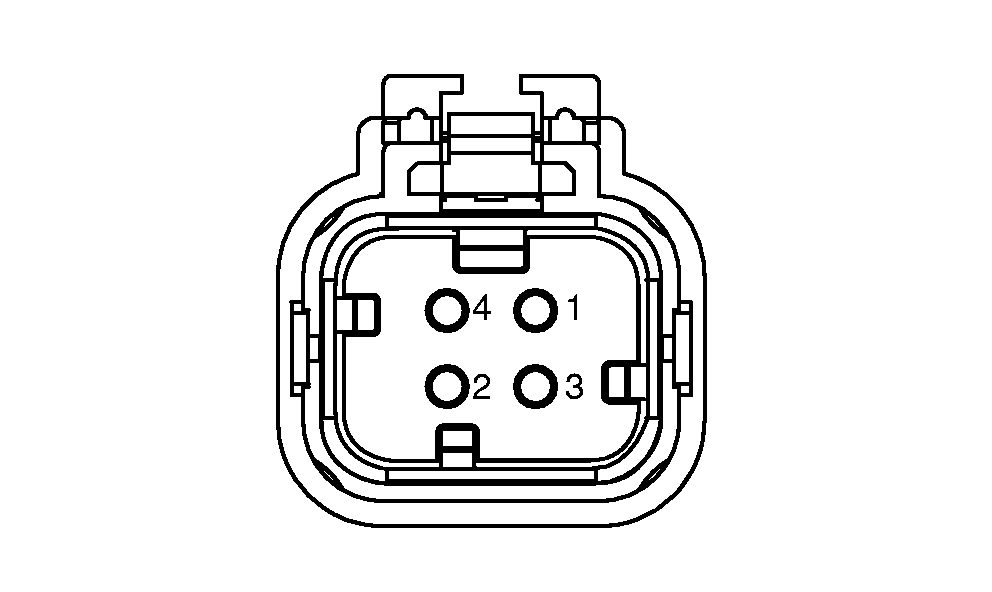
Video Connector Pin Identification
RXA0122385-UN-29NOV11
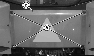
Remove Rear Panel
RXA0128559-UN-05OCT12
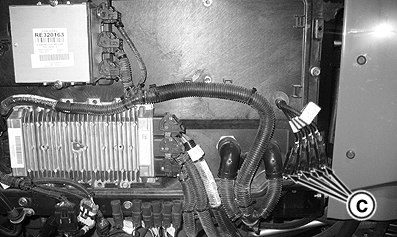
Video Connectors Location
A - Cap Screws
B - Rear Cab Panel
C - Video Connectors for CommandCenter™ and 2630 Display
-
IMPORTANT: Avoid damaging camera by mounting camera securely to equipment and in a location in which camera will not be pinched, crushed, kicked, or knocked off.
NOTE: Camera placement is limited to video camera cable length and safety considerations for camera. Mount camera in a sturdy and secure location. Consider camera field of view when selecting location.
Tractor is equipped with four, four pin video connectors to attach camera(s). Remove cap screws (A), then remove rear cab panel (B) to access connectors (C). Chart shows connector pin/function information.
Pin Number
Function
1
Power
2
Ground
3
Signal
4
Signal—Ground
-
NOTE: The camera connector harnesses are identified with labels: TRACTOR CAM, 2630 CAM1, 2630 CAM2, and 2630 CAM3.
Connect the camera to either of the connectors and the video appears in corresponding video on the display. Example, if a camera is connected into the 2630 CAM 1 connector, camera can be viewed in video 1 on the 2630 display.
Connect camera cable into four pin connectors, route cable and mount camera at desired location.
-
Install back panel on tractor.
|
TO84419,0000374-19-20121005 |