Attach Implements to 3-Point Hitch |
|
|
|
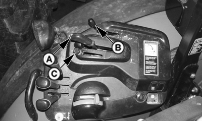
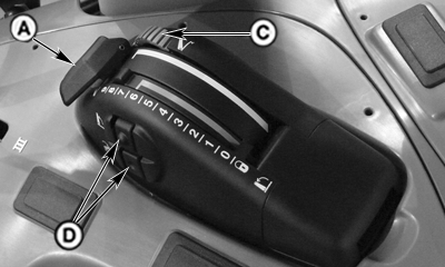
IMPORTANT: Ensure center link and lift link adjustments DO NOT cause implement contact with fenders. NOTE: Engine must be running for 3-point hitch control to work. Before attaching or detaching implement, place load/draft control (B) into lowest setting. (See Adjust Draft Controls in Section 60.) Use position control lever (A) to raise or lower implement. DO NOT use rear quick raise/lower buttons (D). Be sure drawbar will not interfere. If necessary, move drawbar to fully retracted position or remove it. Check for any other potential interference. |
|
SH20560,000012E -19-14JUL08-1/5 |
|
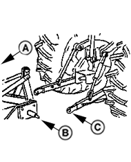
1. Back tractor up to implement (A) so hitch points align. Place transmission in PARK and stop engine. 2. Slip draft links (C) over implement hitch pins (B) and retain with quick-lock pins. 3. Push tab (E) backward and lift locking clip (D) to release center link from transport hook. 4. Attach center link to implement top mast. 5. Adjust center link and lift links as necessary. See "Level Hitch" in this section.
|
|
SH20560,000012E -19-14JUL08-2/5 |
|
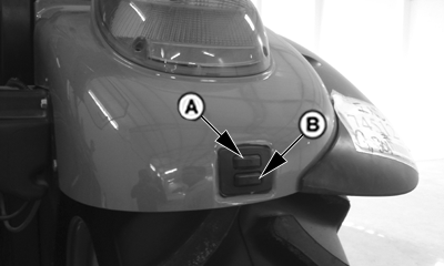
6. Start engine. Using position control lever, slowly raise and lower implement and check for interference. NOTE: If equipped with electrohydraulic hitch use quick raise/lower buttons or fender-mounted switches (A and B) to raise and lower implement and check for interference. |
|
SH20560,000012E -19-14JUL08-3/5 |
|
Standard Telescopic Draft Links
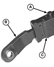
1. Move button (A) toward center of tractor and pull out draft link end (B). Slip draft link end over implement hitch pin. Retain with quick-lock pin. Repeat on other side. 2. Raise or lower draft arms (C) to align ends (B) with arms, then slowly back up tractor to lock ends in place. 3. Perform steps 2-6 from fixed draft links procedure.
|
|
SH20560,000012E -19-14JUL08-4/5 |
|
|
|
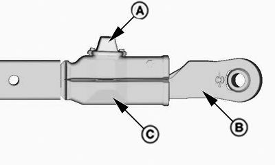
Heavy Duty Telescoping Draft Links
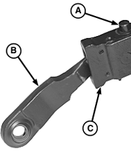
1. Lift lock pin (A) and pull out draft link end (B) to rear. Slip draft link end over implement hitch pin. Retain with quick-lock pin. Repeat on other side. 2. Raise or lower draft arms (C) to align ends (B) with arms, then slowly back up tractor to lock ends in place. 3. Perform steps 2-6 from fixed draft links procedure.
|
|
SH20560,000012E -19-14JUL08-5/5 |
 CAUTION:
Hitch movement can cause injury or death.

