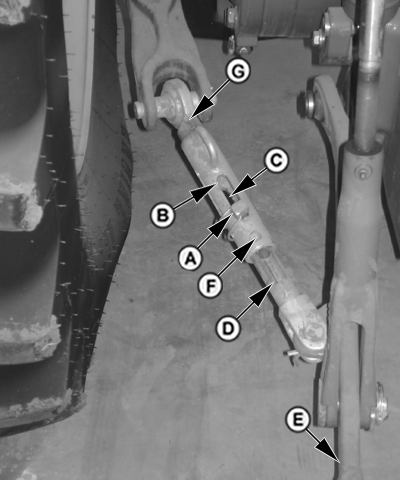
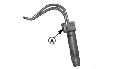
Adjust Hitch Side SwayNOTE: Check implement operator's manual for instruction on whether to allow side sway. If sway is desired, install pin (A) in sway position outer slot (B), ensuring it goes through sway position inner slot (C). If sway is not desired, move draft link (E) to desired position. Install pin (A) in fixed position hole (F) that lines up with one of the holes (not slot) of the inner sliding member (D). Adjust opposite side sway bar to same position. NOTE: Additional fixed positions can be obtained by adjusting threaded end of stabilizer (G). Disconnect inner sliding member (D) from draft link (E). Rotate stabilizer as necessary. Missing thread on stabilizer also acts as a stop indicator.
|
|
SH20560,0000133 -19-14JUL08-1/1 |

