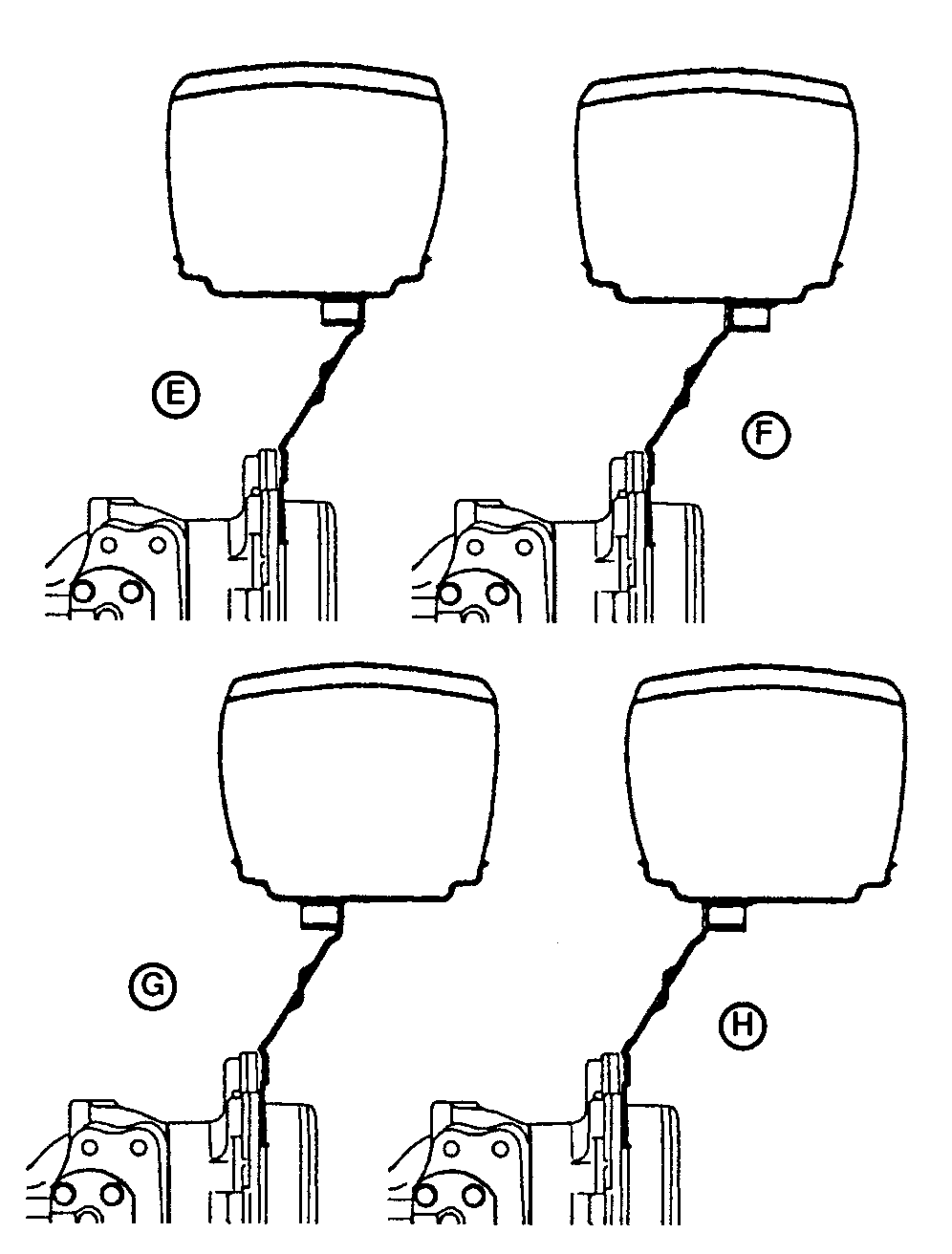
Tread Setting—Multi-Position MFWD Wheels

LV602-UN-22APR94
Tread Setting—Multi-Position MFWD Wheels
Wheel tread on MFWD axle with multi-position wheels can be adjusted by repositioning or exchanging the rims or by reversing the wheel disks.
Wheel tread can also be adjusted by exchanging the complete wheel to the opposite side of the tractor .(This maneuver permits the change from disk-dished-in to disk-dished out operations without disassembling the wheel). When Changing MFWD wheels from one side to other, the arrow on side wall of tire points in the direction of forward rotation. In certain applications, MFWD equipped tractors may operate with the arrows in the opposite direction. See Select Front Tire Rolling Direction.
The relationship of the wheel disk and rim in obtaining the different tread setting is shown in the diagrams, before attempting to change tread settings, will save unnecessary labour.
IMPORTANT: After setting wheel spacing, tighten MFWD wheel rim-to-disk bolts and MFWD wheel disk-to-hub nuts to specification. Drive tractor 100 m (109 yd) and tighten again.
| Item | Measurement | Specification |
| MFWD Wheels | ||
| MFWD Wheel Rim-to-Disk Nuts | Torque | 245 N•m (180 lb-ft) |
| MFWD Wheel Disk-to-Hub Nuts | Torque | 310 N•m (228 lb-ft) |
NOTE: Tread settings are measured at bottom centerline of tire.
|
MULTI-POSITION MFWD WHEELS TREAD WIDTH Centerline-to-centerline |
||||||||
|
Diagram |
||||||||
|
Tire |
A |
B |
C |
D |
E |
F |
G |
H |
|
9.5-24 6PR R1 |
1340 mm (52.8 in.) |
1452 mm (57.2 in.) |
1493 mm (58.8 in.) |
1605 mm (63.2 in.) |
1640 mm (64.6 in.) |
1753 mm (69.0 in.) |
1792 mm (70.6 in.) |
1905 mm (75.0 in.) |
|
12.5/8-16 6PR R4 |
1531 mm (60.27 in.) |
1699 mm (66.88 in.) |
N/A |
N/A |
N/A |
N/A |
N/A |
N/A |
|
AH98466,000069D-19-20090108 |