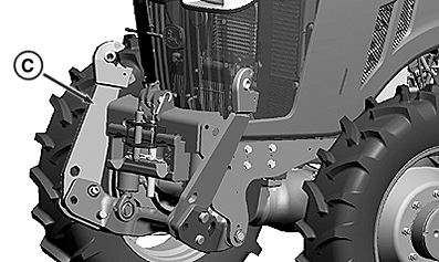
Front Implement Connection
Draft Link Positions
LV16176-UN-12OCT12
LV16177-UN-12OCT12
RXA0153888-UN-19SEP16
RXA0155569-UN-09NOV16
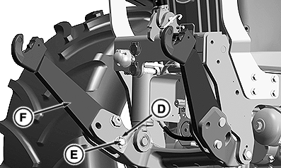
A - Draft Links with Vertical Float Position
B - Draft Links Locked Position
C - Draft Links in Transport Position
D - Retaining Clip
E - Draft Link Pin
F - Draft Link
Set front draft links to float position (A), locked position (B), or transport position (C).
To change setting:
-
Remove retaining clip (D) from pin (E).
-
Lift draft link (F) to relieve pressure from pin.
-
Remove pin.
-
Move draft link to desired position.
-
Reinstall pin and retaining clip.
Draft Link Hook Lock
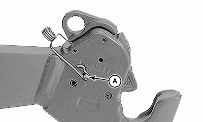
LV16212-UN-22OCT12
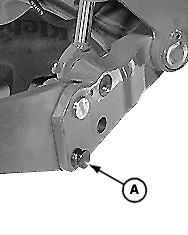
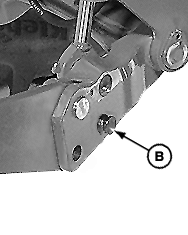
A - Draft Link Locking Pin
 CAUTION: Use draft link locking pins on applications where implement
could be forced up and open unintentionally. Examples are driving
through high-growing bushes, trees, or implements with asymmetrical
load, such as a side-mounted mower.
CAUTION: Use draft link locking pins on applications where implement
could be forced up and open unintentionally. Examples are driving
through high-growing bushes, trees, or implements with asymmetrical
load, such as a side-mounted mower.
-
Install front mounted implement using SCV I. For diverter valve settings, see “Front Hitch and Coupler Operation” in this section.
-
Lower front hitch below the implement connection points.
-
Position coupler ends of lift arms below the implement link pins and slowly raise hitch until coupler ends lock on the pins.
-
Insert draft link pins (A) in both coupler hooks. See your John Deere dealer for locking pins.
Front Hitch Center Link
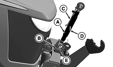
RXA0153887-UN-13SEP16
A - Center Link
B - Storage Handle
C - Locking Clip
D - Turnbuckle
E - Pin and Clip
-
Lower implement to ground.
-
Hold center link (A) and pull on the storage handle (B).
-
Align center link with the top mast of implement.
-
To lengthen or shorten the center link, move locking clip (C) away from center link.
-
Use turnbuckle (D) to adjust length and return locking clip (C) to closed position.
NOTE: Perform additional adjustment as necessary to level implement after cycling front hitch.
-
Install implement pin through center link and retain.
-
Remove implement in reverse order.
NOTE: If front hitch center link must be removed for any reason, support center link and remove pin and clip (E).
|
BH38674,000056C-19-20170110 |