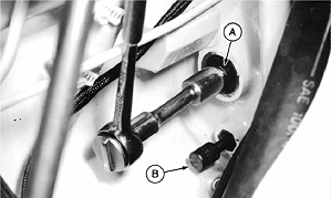
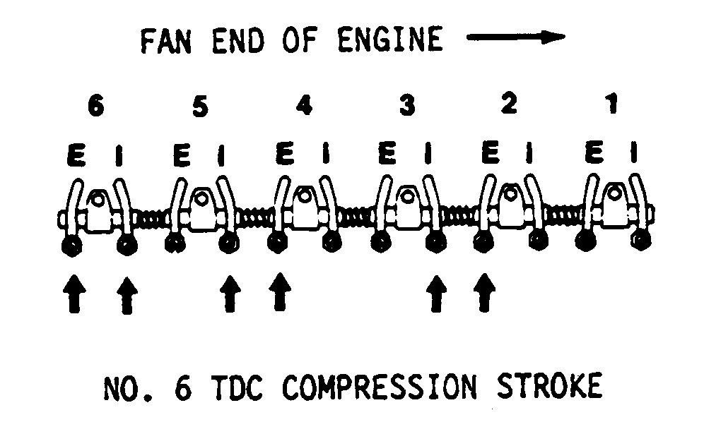
Measure and Adjust Engine Valve Clearance (S.N. -830204)1. Remove parts as necessary.2. Plug all openings. 3. Check crankcase ventilation for restriction. Clean with solvent or diesel fuel. 4. Remove rocker arm cover. 5. Install JDE-81-4 Timing Pin (B) and JDE-81-1 Flywheel Turning Tool (A). 6. Turn flywheel until timing pin goes into hole in flywheel. 7. Use either of the following methods to determine which cylinder is at top dead center (TDC): Try to move both pushrods at number one cylinder. If both are not loose, pull timing pin out of flywheel, rotate flywheel 360°, and insert timing pin. Both pushrods being loose indicates the piston is at TDC on compression stroke. |
|
TX,85,BG730 -19-15FEB97-1/5 |
|
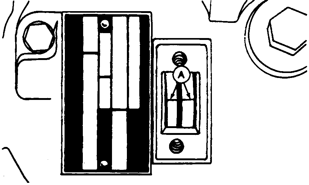
Remove timing hole cover from fuel injection pump. If timing lines (A) are in alignment, number one piston is at TDC on compression stroke. If lines are not in alignment, number six piston is at TDC on compression stroke. |
|
TX,85,BG730 -19-15FEB97-2/5 |
|
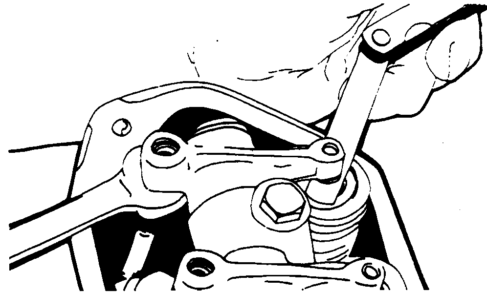
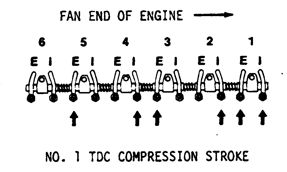
NOTE: Valve clearance can be adjusted whether engine is hot or cold. 8. Measure and adjust valve clearance, first with number one piston at TDC and then with number six at TDC. To change piston position, pull timing pin out of flywheel, rotate flywheel 360°, and insert timing pin. Specification
|
|
TX,85,BG730 -19-15FEB97-3/5 |
|
Specification
9. Clean cylinder head and rocker arm cover mating surfaces. 10. Install rocker arm cover gasket. Do not use sealant on the gasket. |
|
TX,85,BG730 -19-15FEB97-4/5 |
|
11.
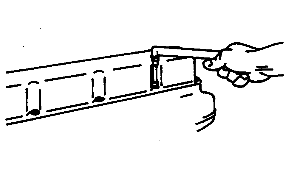
Install rocker arm cover. Tighten screws to 10.8 N·m (96 lb-in).
Specification
12. Remove turning tool and timing pin. 13. Install parts. |
|
TX,85,BG730 -19-15FEB97-5/5 |
