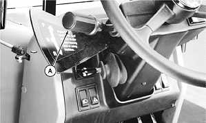
Inspect and Adjust Park Brake (S.N. -872256)1. Park machine on level surface and lower all equipment to ground.2. Move FNR lever (A) to neutral "N". 3. Move park brake switch to ON position. 4. Stop engine.
5. Block wheels to prevent movement. 6. Remove operator's station floor plate. |
|
 CAUTION:
Prevent possible injury from unexpected machine movement. Block wheels to prevent movement of machine during adjustment.
CAUTION:
Prevent possible injury from unexpected machine movement. Block wheels to prevent movement of machine during adjustment.
TX,85,BG732 -19-15FEB97-1/3 |
|
|
|
|
|
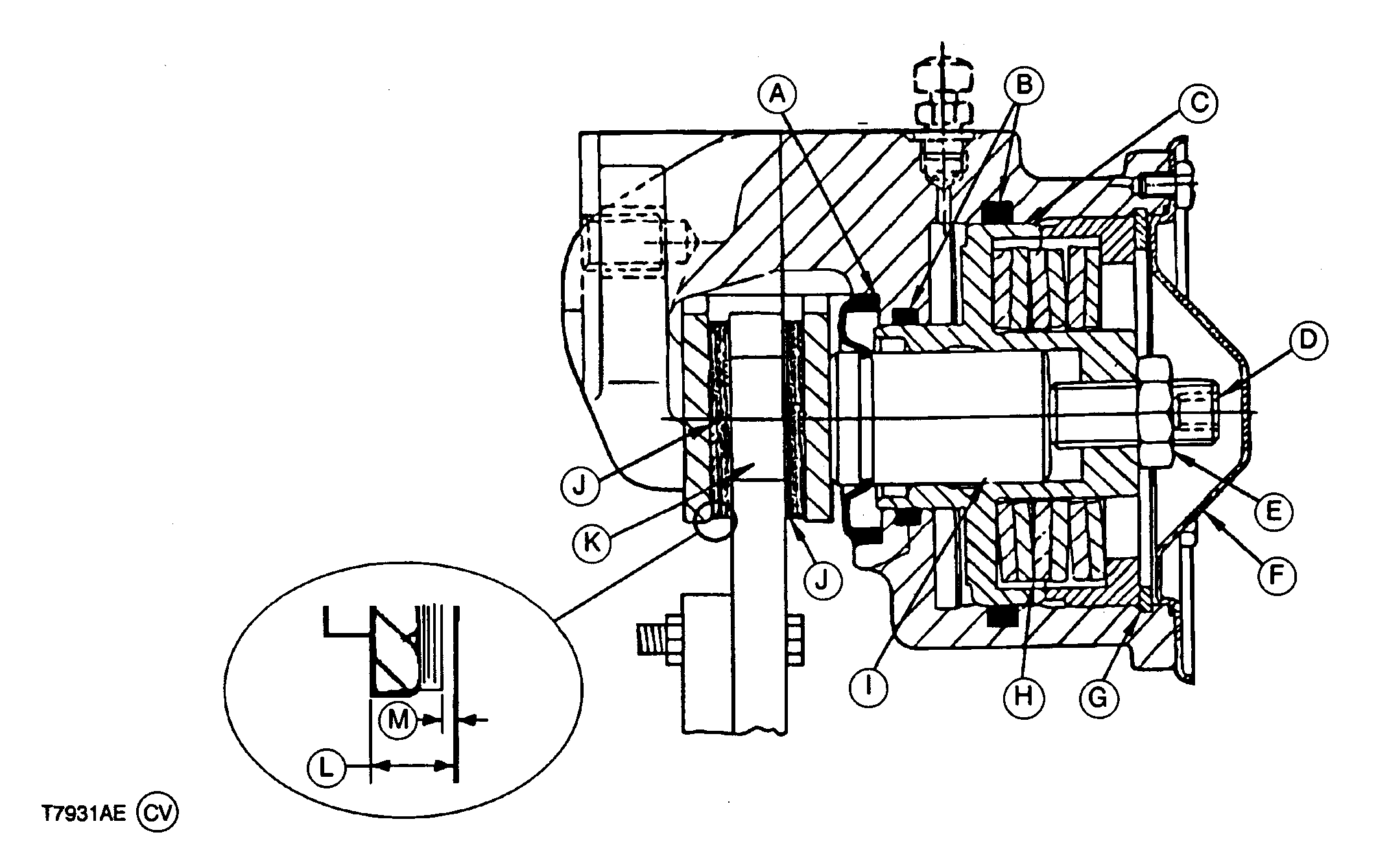
| 7. Check minimum thickness (L) of brake pad and backing plate. If clearances are out of specification, see your authorized dealer for service. If (L) thickness is to specifications, go to next step. |
Specification
|
TX,85,BG732 -19-15FEB97-2/3 |
|
8.
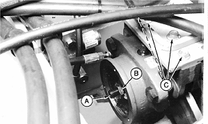
Remove screws and remove sheet metal cover from brake. Loosen lock nut (B).
9. Loosen the four mounting cap screws (C) that hold the park brake to the mounting bracket. 10. Tighten adjustment screw (A) to 68 N·m (50 lb-ft). Specification
11. Tighten the 4 mounting cap screws to 75 N·m (52 lb-ft). Specification
12. Back the adjustment screw off 180° (1/2 turn). This will give approximately 0.5 mm (.02 in.) pad to disk clearance. Specification
13. Tighten the locking nut (B) to 100 N·m (75 ft lb) making sure the adjustment screw does not turn with it. Specification
14. Install sheet metal cover. Tighten cover screws. 15. Install operator's floor plate. |
|
TX,85,BG732 -19-15FEB97-3/3 |