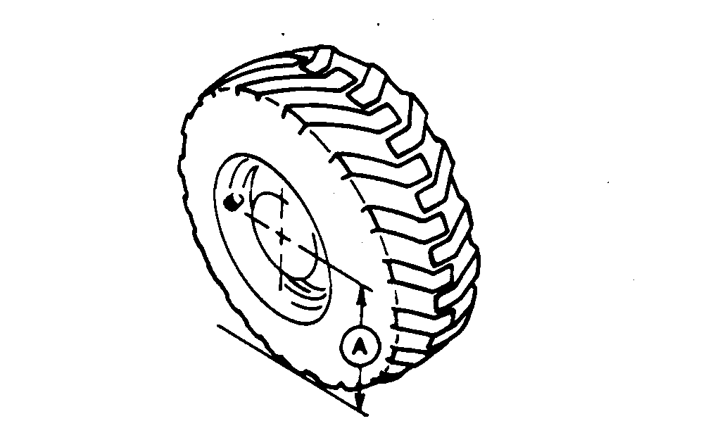
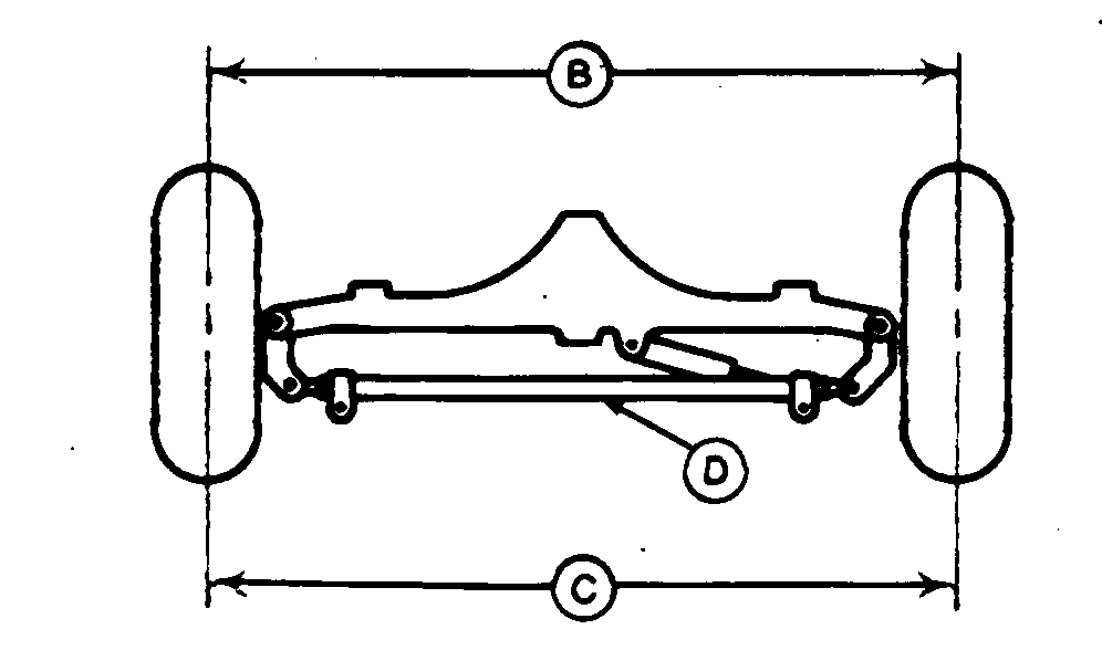
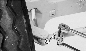
Check and Adjust Toe-In1. Measure distance from ground to center of hub (A).2. At the height from Step 1, make a mark on front (B) and rear (C) of each front tire in center of tread. 3. Measure distance between front marks (B). 4. Measure distance between rear marks (C). 5. MACHINES WITHOUT MECHANICAL FRONT WHEEL DRIVE: The distance between marks on front of tires must be 6 ± 3 mm (1/4 ± 1/8 in.) less than distance between marks on rear of tires. 6. To adjust toe-in, loosen both tie rod clamps (E) and turn tie rod tube (D). 7. Turn clamps so that cap screws are towards rear of machine and tipped down approximately 45°. 8. Tighten clamp cap screws to 95 ± 14 N·m (70 ± 10 lb-ft). Specification
9. MACHINES WITH MECHANICAL FRONT WHEEL DRIVE: The distance between marks on front of tires must be 6 ± 3 mm (1/4 ± 1/8 in.) less than distance between marks on rear tires. |
|
TX,90,RR4054 -19-09DEC93-1/2 |
|
10.
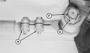
To adjust toe-in, loosen nuts (H).
11. Remove cotter pin (G) and nut (F). Remove tie rod end from steering arm. 12. Turn tie rod end on tie rod to get proper toe-in. 13. Place tie rod end in steering arm. Install nut (F) and tighten to 220 N·m (162 lb-ft). Specification
14. Install cotter pin (G) and tighten nuts (H). |
|
TX,90,RR4054 -19-09DEC93-2/2 |


