Winch BRAKE OFF Adjustment-If Equipped
1.
Install frame locking bar.
2.
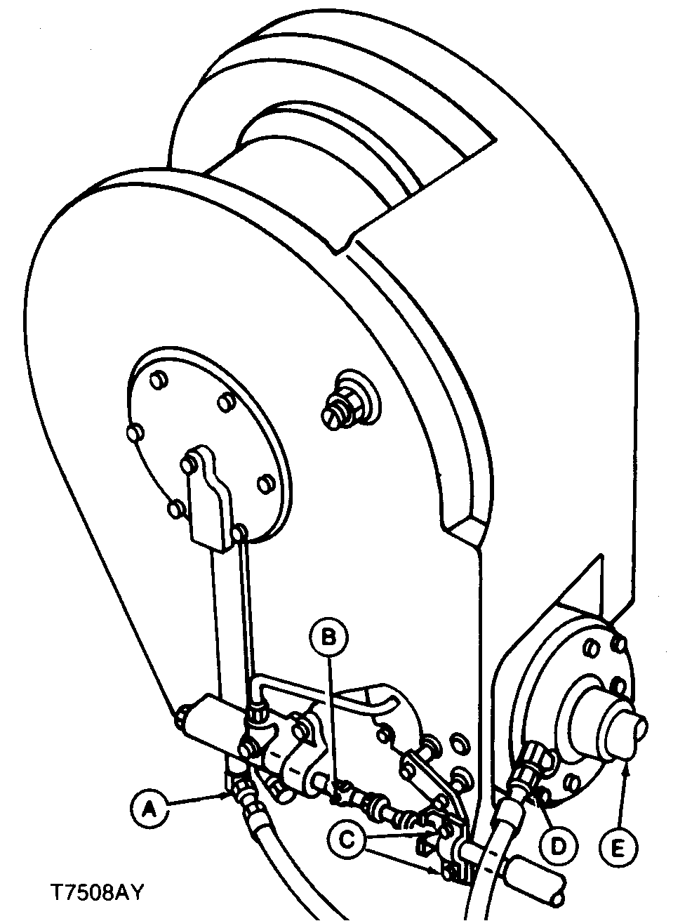
Remove the yoke (C) from the bellcrank on 4000 Series Winch.
Remove the yoke (B) from the valve spool on 6000 Series Winch.
IMPORTANT:
Winch control valve spool must be in freespool detent to correctly adjust linkage.
3.
Push winch valve spool IN, as far as possible, into freespool detent.
|
6000 Series Winch Shown
4000 Series Winch Shown
|
|
|
CED,OUO1079,221 -19-26APR00-1/8
|
|
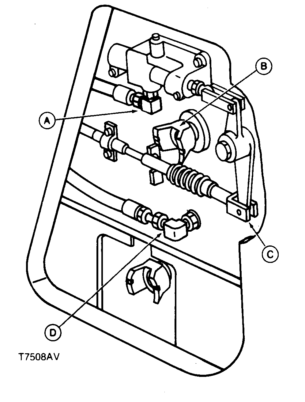
4.
Secure the lever to the rear of the BRAKE OFF position.
|
|
|
|
CED,OUO1079,221 -19-26APR00-2/8
|
|
IMPORTANT:
On 4000 Winch, do not pull out of free spool detent. Just remove slack in bellcrank linkage.
5.
With the 4000 winch bellcrank or 6000 winch valve spool in free spool detent position, pull cable with 44.5 N (10 lb-force).
Specification
|
Cable Pull
-Force
|
44.5 N (10 lb-force)
|
On 4000 Series Winch only, apply 22.2 N (5 lb-force) to bellcrank toward cable end.
Specification
|
Cable Pull
-Force
|
22.2 N (5 lb-force)
|
6.
Adjust the 4000 winch yoke to align with hole in bellcrank. Adjust the 6000 winch yoke to align with valve spool.
7.
Connect the yoke to the 4000 winch bellcrank (or 6000 winch valve spool) and install pin.
|
|
|
|
CED,OUO1079,221 -19-26APR00-3/8
|
|
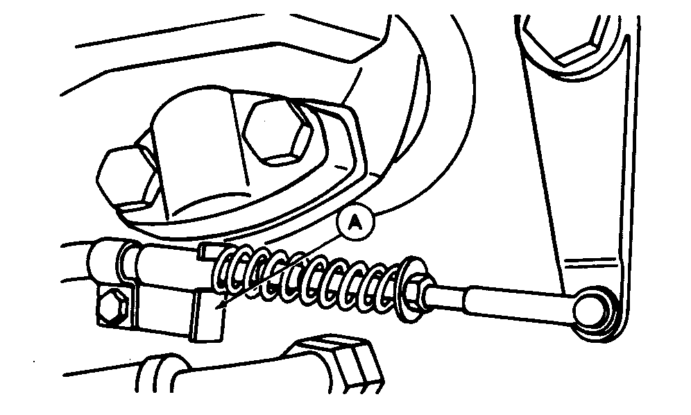
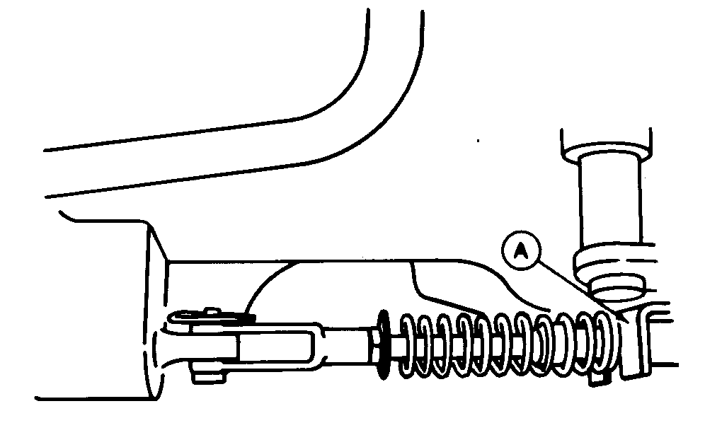
8.
Move control lever to PARK (hold) position.
9.
Slide bracket (A) so that lip contacts spring.
10.
Tighten bracket and control cable cap screws.
|
4000 Series Winch Shown
6000 Series Winch Shown
|
|
|
CED,OUO1079,221 -19-26APR00-4/8
|
|
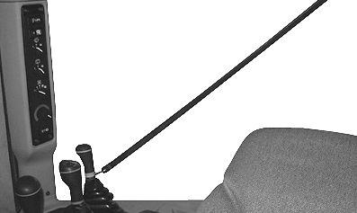
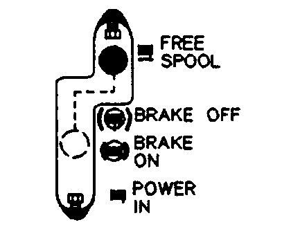
11.
Run engine at slow idle.
12.
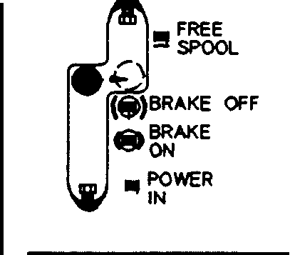
Move control lever to FREE SPOOL position and release lever. There must be 3-5 mm (0.120-0.160 in.) distance between lever and stop screw.
Specification
|
Lever and Stop Screw
-Clearance
|
3-5 mm (0.120-0.160 in.)
|
|
|
|
|
CED,OUO1079,221 -19-26APR00-5/8
|
|
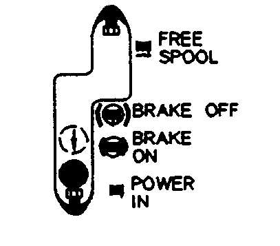
13.
Slowly move control lever to POWER IN position until drum turns. There must be 6-8 mm (0.240-0.320 in.) distance between lever and stop screw.
Specification
|
Lever and Stop Screw
-Clearance
|
6-8 mm (0.240-0.320 in.)
|
Adjust as required.
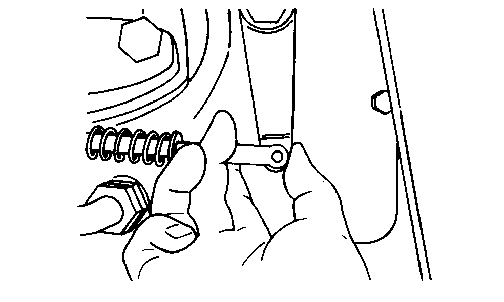
14.
While POWER IN is engaged, release lever. Lever must return to PARK (hold) when released from any POWER IN position. If lever does not return, go to step 9 and increase return spring tension.
|
|
|
|
CED,OUO1079,221 -19-26APR00-6/8
|
|
15.
Move winch control lever to FREE SPOOL position detent.
|
|
|
|
CED,OUO1079,221 -19-26APR00-7/8
|
|
16.
Pull lever left with approximately 22 N·m (5 lb-force), then move lever forward through gate. Lever must move freely through gate and not contact gate slot surfaces. If lever contacts gate slot surfaces, repeat steps 2 through 10.
|
|
|
|
CED,OUO1079,221 -19-26APR00-8/8
|
|