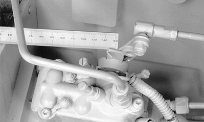
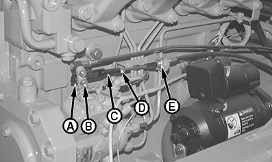
Adjust Engine Speed Control Linkage (S.N. -882699)1. Move accelerator pedal to fast idle position.2. Measure injection pump lever override. Override must be with specification. Specification
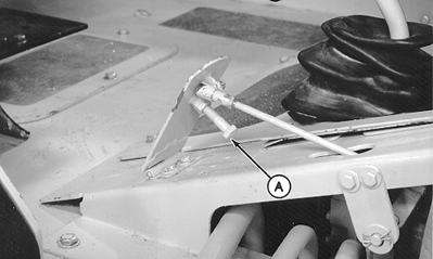
3. Adjust stop screw (A) (located at bottom of accelerator pedal) to provide proper override. 4. Release accelerator pedal to slow idle position. Check override. Slow idle override must be to specification. Specification
If slow idle override is less than minimum distance, shorten speed control rod by turning ball joint at injection pump until minimum override can be obtained. 5. Check fast idle again for minimum override. Specification
If fast idle override is less than minimum distance, check and adjust pedal and pump rods to initial lengths. Rod - Specification
|
|
OUO1030,0000750 -19-28FEB07-1/4 |
|
Specification
6. Repeat steps 1-5. |
OUO1030,0000750 -19-28FEB07-2/4 |
|
7.
On machines (S.N. -872334) with hand throttle, perform the following:
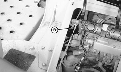
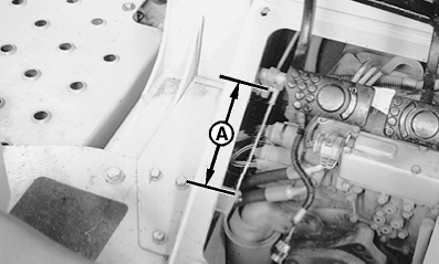
a. Disconnect hand throttle cable from cross shaft. b. Allow accelerator pedal to go to slow idle position (fully up). Make sure hand throttle is at slow idle (fully down). c. Adjust ball joint (B) on end of throttle cable so threaded end fits into hole of bellcrank on cross shaft. NOTE: Hand throttle cable has more travel available than is utilized by this machine. d. Move hand throttle from slow to fast idle to check injection pump lever override. Override should match pedal override. 8. On machines (S.N. -872334) without hand throttle, adjust stationary rod until length (A) is to specification. Specification
|
|
OUO1030,0000750 -19-28FEB07-3/4 |
|
9.
On machines (S.N. 872335- ) with hand throttle, perform the following:
a. Disconnect hand throttle cable yoke (C) from pin on injection pump lever. b. Allow accelerator pedal to go to slow idle position (fully up). Make sure hand throttle is at slow idle (fully down). c. With cable attached to support bracket adjust cable yoke (C) to fit onto guide pin (B) on injection pump. Tighten jam nut (D). Yoke should move on guide pin without binding. NOTE: Hand throttle cable has more travel available than is utilized by this machine. d. Move hand throttle from slow to fast idle to check injection pump lever override. Override should match pedal override. |
|
OUO1030,0000750 -19-28FEB07-4/4 |
