Toe-In Check and Adjust (S.N. -888003) |
|
|
|
1.
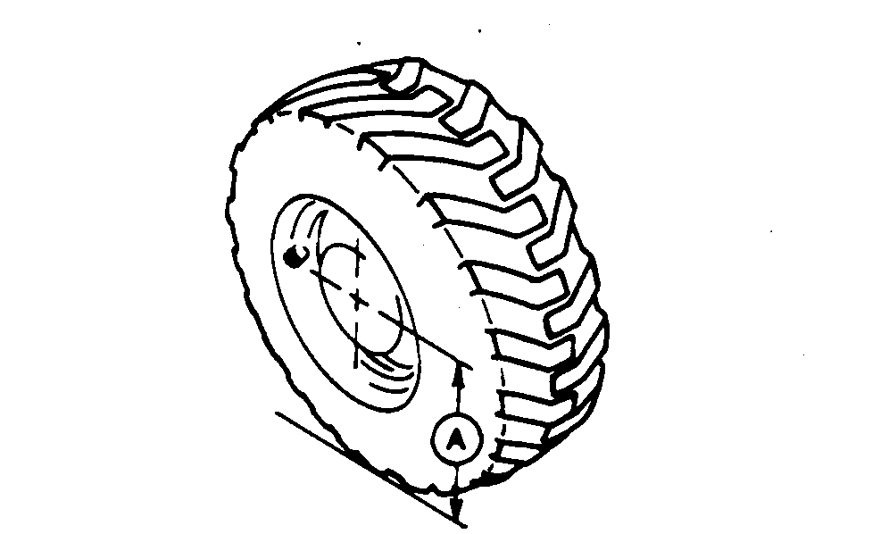
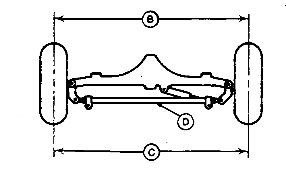
Measure distance from ground to center of hub (A) and make a mark on front (B) and rear (C) of each front tire in center of tread.
2. Measure distance between front marks (B). 3. Measure distance between rear marks (C). 4. The distance between front marks must be less than distance between rear marks by the following amount. Specification
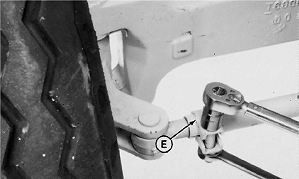
Machines Without Mechanical Front Wheel Drive: 1. To adjust toe-in, loosen both tie rod clamps (E) and turn tie rod tube (D).2. Turn clamps so that cap screws are toward rear of machine and tipped down approximately 45°. 3. Tighten clamp cap screws to specification. Specification
Machines With Mechanical Front Wheel Drive: |
|
VD76477,0001451 -19-21FEB07-1/2 |
|
1.
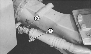
To adjust toe-in, loosen nuts (F).
2. Turn rod end (G) to get proper toe-in. 3. Adjust toe-in equally on both tie rods. 4. Tighten nuts to specification. Specification
|
VD76477,0001451 -19-21FEB07-2/2 |


