Rotating Mower Deck
Rotating Mower Deck for Service
-
Raise the mower deck completely.
-
Park the machine safely. (See Parking Safely in the Safety section.)
-
Remove the front (A) and rear (B) drive shaft shield chains from the brake cross shaft.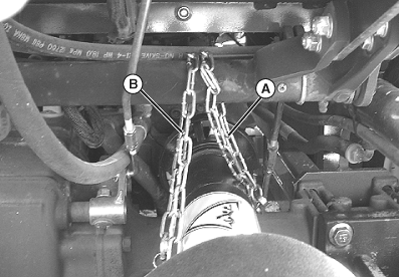
TCAL46574-UN-12APR13 -
 CAUTION: Engage service latches. Mower deck can drop if hydraulic
pressure is lost.
CAUTION: Engage service latches. Mower deck can drop if hydraulic
pressure is lost.Engage the service latches.
-
60 and 72 Inch Mower Decks Only: Remove the spring pin (C) from the drilled pin (D) holding the anti-scalp wheel bracket (E) onto the left side of mower deck.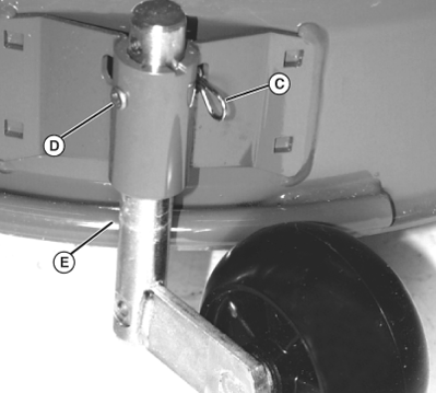
TCAL46575-UN-12APR13 -
Remove the anti-scalp wheel from mower deck.
-
Unlock and open service hatch (F) on machine.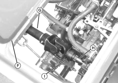
TCAL46576-UN-12APR13 -
Pull forward on the coupler ring (G) located on the mower deck PTO drive shaft (H. Pull the drive shaft off of machine PTO output shaft (I).
-
Remove the retaining ring (J) from the hanger pin (K).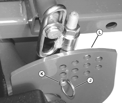
TCAL46577-UN-12APR13 -
NOTE: To return the mower deck to its original cutting height, note the hole location that the hanger pin was installed in before removing the hanger pin.
Remove hanger pin from hole in adjustment plate (L).
-
Repeat for the other side of mower deck.
-
Lower rear of mower deck down to the ground. PTO drive shaft (M) will fall clear of front axle.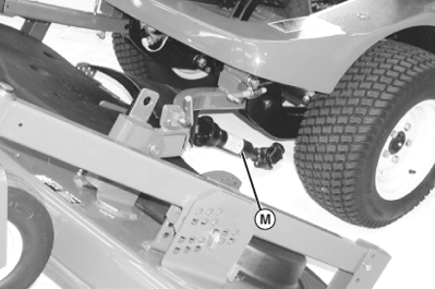
TCAL46578-UN-12APR13 -
Pull mower deck service lock handle (N) out and rotate back until the spring is compressed and pin (O) is locked into slot.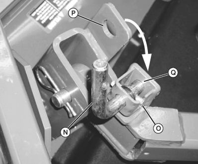
TCAL46579-UN-12APR13 -
Rotate the mower deck back until the hole in the deck bracket (P) is aligned with the service lock hole (Q).
-
Rotate the service lock handle (N) forward to extend the pin into deck bracket hole (P).
Rotating Mower Deck for Operation
-
Pull mower deck service lock out of deck bracket.
-
Rotate deck forward, keeping mower deck drive shaft from digging into ground.
-
Route mower deck drive shaft up on top of machine front axle, and connect to machine PTO output shaft on transaxle.
-
Attach the front and rear drive shaft shield chains to the brake cross shaft. Adjust the chains as required to maintain minimal slack as the mower deck is raised or lowered to its travel limits.
-
Rotate mower deck to level position.
-
Install rear hanger pins into holes in rear adjustment plates that correspond to desired cutting height.
-
Install retaining rings on left and right side hanger pins.
-
Install anti-scalp wheel onto mower deck.
-
Unlock service latches.
-
Lower mower deck to ground.
-
Adjust anti-scalp wheel to 6 mm (1/4 in.) above level ground.
|
AP43109,00002B9-19-20130415 |