Assemble Frame
-
Park machine safely. (See Parking Safely in the SAFETY section.)
-
Remove engine guard (if equipped) by removing four carriage bolts, washers, and locknuts (A) and engine guard (B).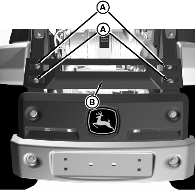
TCT013262-UN-19FEB16 -
 CAUTION: Avoid injury! Bumper weighs approximately 41 kg (90
lbs), John Deere recommends that two people be used when removing
bumper from machine.
CAUTION: Avoid injury! Bumper weighs approximately 41 kg (90
lbs), John Deere recommends that two people be used when removing
bumper from machine.
Remove two M12 nuts (C) and two M12x30 flange head bolts (D). Remove bumper (E) and rear grille (F).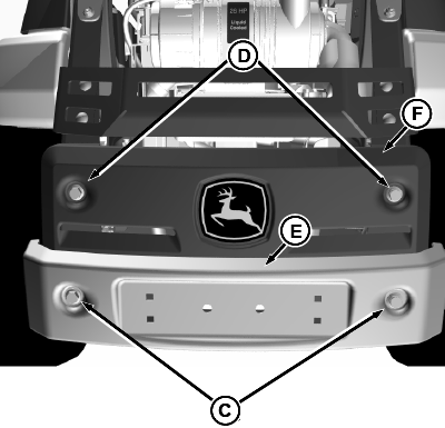
TCT013263-UN-19FEB16 -
NOTE: Refer to Verify Frame Member Reinforcement in Preparing Vehicle section to determine if the following two steps are necessary.
Remove three M12x30 flange head bolts on each side holding the rear frame members (G). Remove frame members and replace with reinforced frame members provided. Tighten frame flange head bolts to: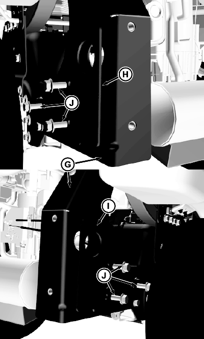
TCT013264-UN-19FEB16Item Measurement Specification Flange Head Bolt Torque 115-122 N•m (85-90 lb-ft) -
Install left plate (H) and right plate (I) with three M12x30 flange head bolts, washers, and locknuts (J) on each side. Do not tighten.
-
Install two side brackets (K) to the steel bumper (L) with four M10 flange head bolts (M) and locknuts. Leave slightly loose until tops of brackets are secure in place.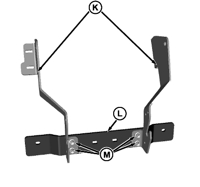
TCT013265-UN-22FEB16 -
Install rear grille (F) using existing hardware.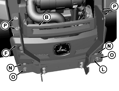
TCT013266-UN-19FEB16 -
Install steel bumper (L) to machine using spacers (N), M12x70 bolts, and M12 locknuts (O). Tighten locknuts to:
Item Measurement Specification Locknut Torque 115 N•m (85 lb-ft) -
NOTE: On models with an engine guard (B), be certain to install before securing top of brackets to machine.
Secure tops of brackets with four M10x30 flange head bolts, washers, and locknuts (P) in the mounting location for the engine guard. Tighten all bracket hardware.
-
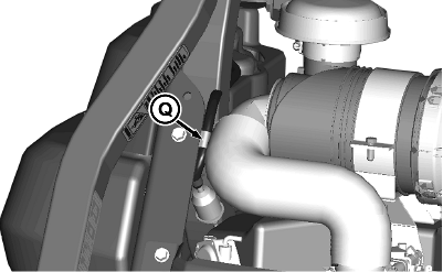
NOTE: On some models, there is a fuel line clamp (Q) located at one of the holes needed for mounting one of the reinforcement plates. Be certain to install fuel line clamp as shown.
TCT013267-UN-19FEB16
Install reinforcement plates (R) with U-bolts and supporting hardware (S).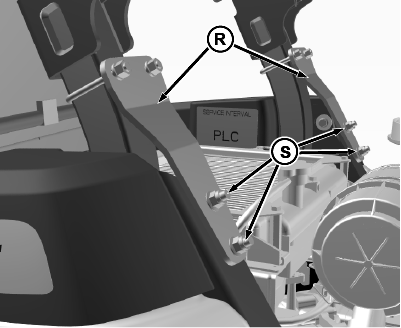
TCT013268-UN-19FEB16 -
Tighten all hardware.
|
MX00654,00000AB-19-20160210 |